
Using Altair Inspire for Quick Topology Optimization
One topic we are hearing a lot about from our customers is the idea of Topology Optimization or Lightweighting design. Thankfully, Altair has some of the most robust tools for this application. Altair Inspire is a simple yet powerful tool for finding optimized designs.
With Inspire, it’s just a few simple steps to get to your optimized shape. I can create the initial design right inside of Inspire, so it’s not necessary for me to use a separate CAD or geometry creation tool prior to optimizing. In this scenario, my goal is to reduce the mass of my shelf bracket while maintaining the desired load, which is 50 lbf/in. The initial design has a weight of 2.13 Lbs.
The first step is to set up your Load Case - Identify the Supports, and for this example, those will be the holes on the upper and lower portions of the geometry and apply your load. You can choose to apply pressure to an entire surface, a concentrated load at any specific point on the design or torque on a surface or center of a hole. For this example, I will use a pressure across the entire surface on top of the bracket, which is where the shelf will sit, shown below in Figure 1.
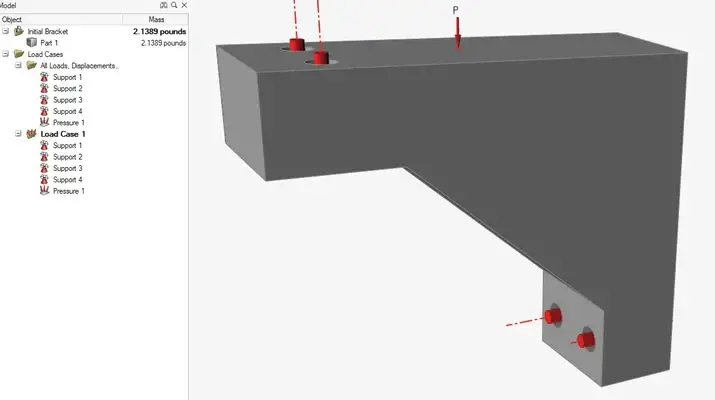
Figure 1: Applying load (shelf) on top of bracket as pressure
Then it’s as easy as running the Optimization. Once you open the Optimization settings (Figure 2), you can choose from a few options for the Optimization type – Maximize Stiffness, Maximize Frequency and Minimize Mass. For this scenario, I am going to choose Maximize Stiffness since my shelf needs to maintain its structure as loads are applied. I apply my Load Case that I just set up and hit Run.
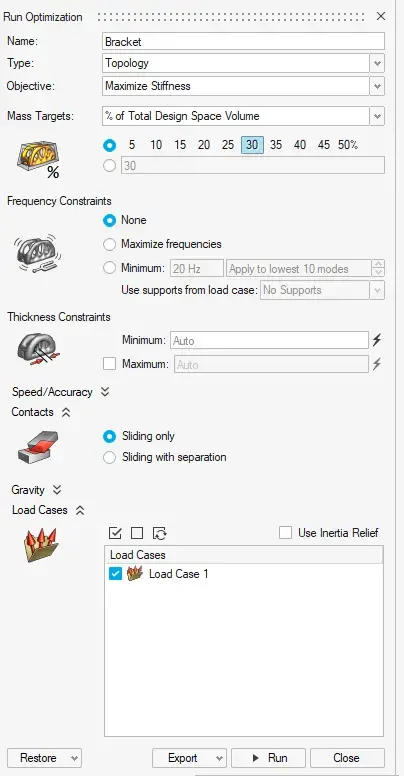
Figure 2: Optimization Wizard with all options
Once the optimization scenario is complete, you can see there are gaps of material that aren’t needed to maintain the design integrity (Figure 3), mainly on the back side of the bracket and the rib in the middle.
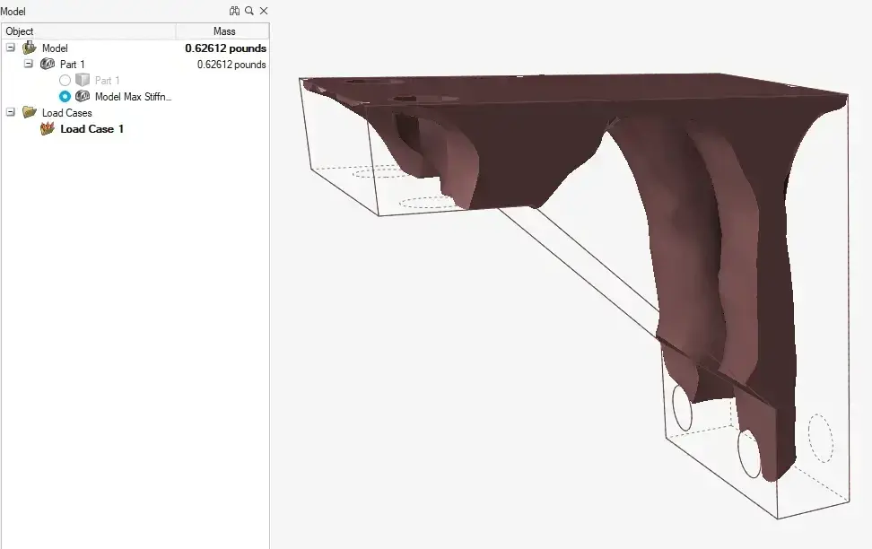
Figure 3: Optimization result showing material needed to maintain desired load
From the Optimization Results window, I have the option to Analyze the part to get results for Stress, Strain and Displacement. Once I do that, I get a Max Stress of 2.54 lbf/in2, shown in Figure 4.
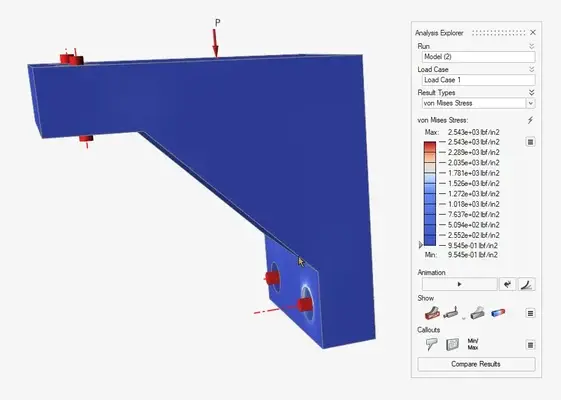
Figure 4: von Misses Stress result from initial Load Case
Let’s use that data and make a few design changes to see how it impacts my Max Stress. With thinning the rib in the middle and cutting out some material on the back, you can see our mass went down to 1.37 lb, which is a 66% reduction. However, our max stress increased to 2.95 lbf/in2, shown in Figure 5.
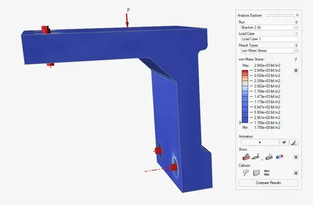
Figure 5: von Misses Stress result from second design iteration
Our max stress increased; however, we are still maintaining our design intent because our max stress is still significantly less than the aluminum yield stress. Because I always want to have 3 designs to choose from, I will try one other option as well. Let’s remove the rib all together and thicken the top face (Figure 6).
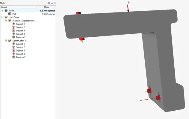
Figure 6: Third design iteration
The weight is nearly identical as scenario number two, but our new Max Stress is 2.38 lbf/in2, which is nearly 70% decrease in Max Stress (Figure 7).
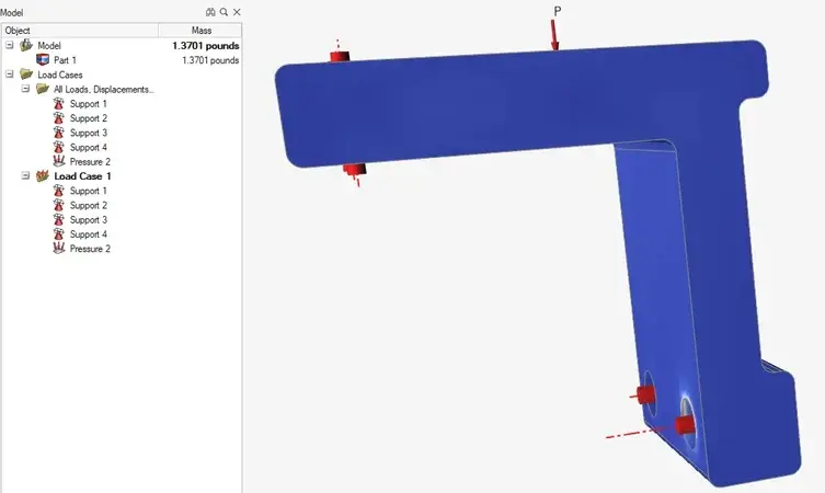
Figure 7: von Misses Stress result from third design iteration
In this example, I was able to run through 3 separate design scenarios in just a couple steps.
- Set up scenario – Supports and Loads
- Choose Optimization options
- Run Optimization
From there it was hitting the analyze button to get Stress and Displacement to make sure I am getting the most optimized design.
Another awesome feature in Inspire is the ability to quickly compare different design scenarios using the Compare feature (Figure 8).
.gif)
Figure 8: GIF showing quick comparison between three design iterations
Overall, Altair Inspire boasts a very intuitive interface that allows users to create geometry, run quick simulations, and optimize parts all in the same interface. For more information or to see Altair Inspire in action, click here.