
TrueInsight
Siemens/Altair Channel Partner
Menu


Using PollEX for DFM and PCB Design Verification
Altair PollEx is a powerful PCB verification tool with built in tools for Design for Manufacturing. Check out how to set up DFM within PollEx.
As technology evolves, more and more products are being manufactured with printed circuit boards (PCB). One of the biggest challenges with PCB design is making sure designs can be easily manufactured, while still meeting all design objectives. On a typical PCB board there could be hundreds of components and thousands of things to check prior to manufacturing. This is where the power of Altair PollEx comes into play. In today’s blog I am going to show you how you can easily run a Design for Manufacturing (DFM) check on an example PCB.
Step 1: Import a PCB into PollEx
PollEx has capabilities to import various ECAD formats, in our case I am going to import a board from Altium directly into PollEx for Verification. Whereas, in other verification tools they can only import Gerber-based files, in PollEx we can import both Gerber and ECAD files!
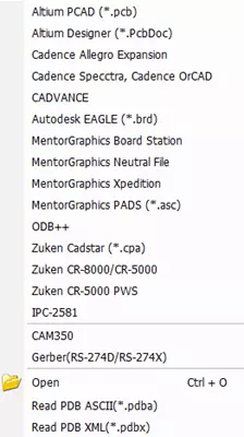
Figure 1: PollEx ECAD Import Files
After you successfully import a board into PollEx, the interface will show the board directly in the main window. PollEx has capabilities to visualize all components and layers. In my case, I visually review the imported board.
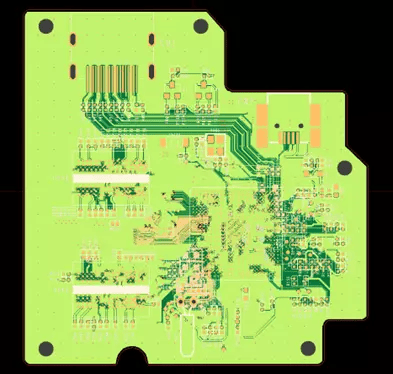
Figure 2: Imported PCB in PollEX
PollEx also gives the user the ability to confirm that all appropriate components were imported into the model, by clicking on the components tab. The Components list will list all components on the PCB that were imported in.
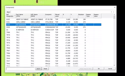
Figure 3: Component List in PollEx
Step 2: Set DFM Requirements
PollEx has a variety of verification tools built into the interface in addition to common verification checks like DFM, DFE, and DFA are integrated into PollEx. In our case, we want to run a DFM verification to make sure our PCB can be easily manufactured. To do that, we go to the DFM tab in PollEx and specify DFM input.
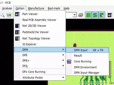
Figure 4: DFM Verification Location
As soon as a user clicks on DFM input, PollEx will open up its large list of DFM design constraints. The great thing about PollEx is that these rules can be customized and saved to meet specific company manufacturing requirements. There are over 158 advanced rules for DFM ranging from Board, Component, Package, Pad, Drill, Tooling, and PCB checks. In our case, I am going to first start with specifying the default board and component level verification checks.
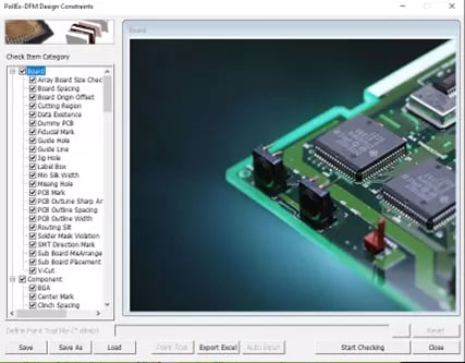
Figure 5: DFM Verification Constraints
The power of PollEX is it gives users the ability to customize verification rules to meet specific manufacturing criteria. In my case, I am going to customize one of my verification rules to meet a specific manufacturing drill size for a 1mm hole size.
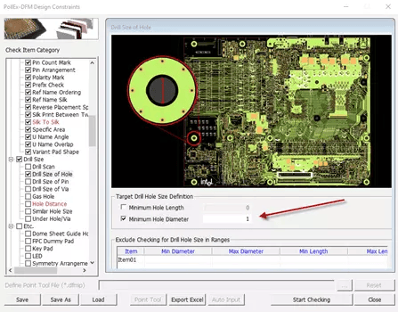
Figure 6: Customized Target hole Drill Size
Step 3: Run DFM Check and Visualize DFM Results
After applying all my DFM verification checks, I can hit the option to start checking and PollEx scan my board to check every single design check I have specified. Verification checks are done in a matter of seconds, and PollEx will show which checks Pass and Fail.
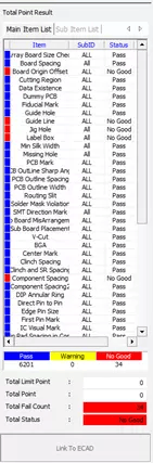
Figure 7: DFM Verification Results
In my case, I obtain results in less than a minute and I can see that over 6000 of my items Pass, while 34 Fail. If I click on the failed items with a left mouse button click, it will illustrate which item is failing. Lets click on the component spacing which is failing.
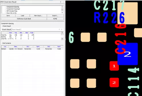
Figure 8: DFM Results Component Spacing Option
As soon as I click on the failed item, it will update in the main graphical window of PollEx for me to visualize. I can clearly see why this item is failing, as the components C216 and R226 are too close together and overlapping., which would result in this board not being able to manufactured correctly.
Through the power of PollEx’s verification checks, PCB designers can check and evaluate boards efficiently and accurately. If you have any additional questions about PollEx’s verification or simulation capabilities, reach out to your TrueInsight Account manager or use our Contact us Form and we will respond as soon as possible!