
TrueInsight
Siemens/Altair Channel Partner
Menu


Using Altair Solutions to Create a Robotic Car Part 1
Part 1 of our series aimed at using Altair solutions to create a robotic car, starting with Altair PSIM
In many of our blogs, we often discuss how the wide variety of software provided by Altair can be beneficial to a range of engineering applications. One thing, though, that many of the previous blogs and videos have in common is that they all exist entirely in simulation. To demonstrate the Altair suite of software in a more concrete environment, we will begin walking through a multi-stage project that combines design, simulation, and real-world application. The final goal of this long-term project will be to create a small robotic car capable of performing some autonomous tasks. This will include powering the motors, implementing a steering control, and modelling other subsystems, as well as their interactions with each other.
To begin, we will start with designing the power supply for the two DC motors used to drive the car. We will use Altair PSIM to design the DC-DC power converter for the motors. We will start this project knowing that we have an 11.1 V battery available, and the two drive motors are designed to operate up to 6 V. We can use this information to begin the design process for the buck converter. For this stage of the project, we are only concerned about the voltage delivered to the motors, not necessarily the speed of the motors themselves. For a more fine-tuned system, we would want to return to this subsystem and include a speed measurement system and update the feedback loop of the controller.
From here, we will need to start with some basic measurements of the motor, including the armature resistance and inductance. This was accomplished using a device called an Analog Discovery Kit, which can function as a voltage supply, oscilloscope, wave generator, and several other useful ‘benchtop’ accessories. Using this tool’s capabilities, the motor armature resistance was found to be approximately 10 Ω and the armature inductance was found to be approximately 1.6 mH. We can modify the typical topology of a buck converter to include these elements of the load as components of the circuit.
From there, we can begin to configure the switch, which will be an IRFZ44N MOSFET. In PSIM, we can model this as a level 1 MOSFET, allowing us to define additional characteristics of the component, as shown in Figure 1.
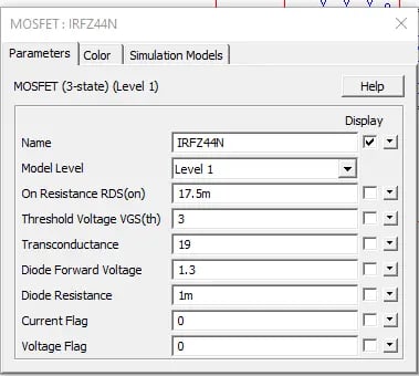 Fig 1. Level 1 MOSFET customization for IRFZ44N
After defining our switch, we can begin to build the rest of the buck converter. We will be using a ‘low-side’ configuration to increase the safety of the circuit. This just means that the source pin of the FET is grounded and a lower voltage across the FET can enable switching. Figure 2 shows the completed schematic for the buck converter with an approximated load.
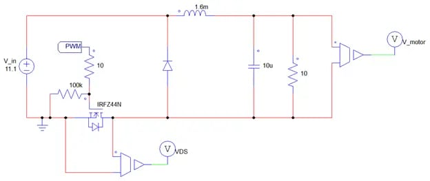 Fig 2. Low-side buck converter configuration
You will most likely notice that the MOSFET is being driven simply by something labelled “PWM.” This label in our model connects to the gate driver subcircuit shown in Figure 3, which will generate the pulse-width modulated signal (PWM) that will drive the MOSFET, causing it to “open” and “close.” PSIM has a library of integrated circuits (ICs) already built-in, including the TC4428 that is used in the model we are building. The input to the IC will be the 100 kHz square wave operating from 0-3.3V (the range of the pin we will use on our microcontroller in a later portion of this project). Since the desired output voltage is 6V, the duty cycle of the switch should be 6V/11.1V ≈ 0.55, which means the input duty cycle to the gate driver should be 1-0.55=0.45, due to the inverting relationship between the input and output.
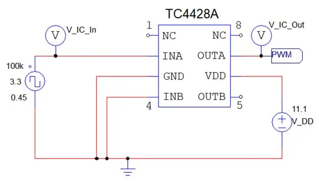 Fig 3. TC4428 Gate Driver subcircuit
After running the simulation outlined above, we can measure a few key outputs of this circuit. First, we will want to make sure the gate driver is functioning as anticipated. We are using the inverting output of the TC4428, which means that the duty cycle will be inverted (if I provide a TRUE or ‘high’ logic input, the output should be FALSE or ‘low,’ and the opposite is true). From Figure 4, we can see that we are getting the expected results. When the input (green) is low (0 V), the output (red) is high (11.1 V); subsequently, when the input is high (3.3 V), the output is low (0 V), which means the gate driver is functioning as anticipated.
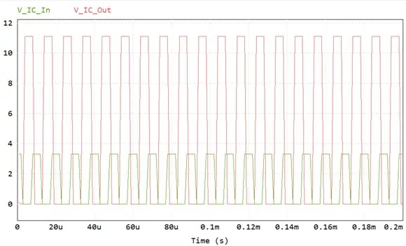 Fig 4. TC4428 Gate Driver input and output
Next, we need to ensure that our gate driver is causing our specific MOSFET to switch appropriately. Figure 5 shows that we are achieving proper switching from 0 V to the supply voltage, 11.1 V at the correct frequency and duty cycle.
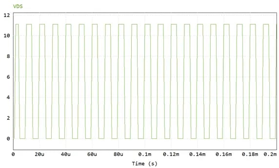 Fig 5. Drain-source voltage indicating switching of MOSFET
Finally, we can verify that the voltage across the motor is the expected 6 V. Figure 6 shows that we can expect some minor overshoot and a settling time of approximately 1 ms in our open-loop model.
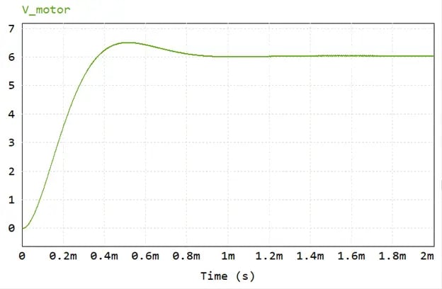 Fig 6. Output voltage of buck converter across load
Once we are satisfied with the results of our simulation, we can begin to build the real-world circuit. Figure 7 shows the completed setup on a breadboard with the motor in place of the load. The yellow wire that goes off-screen to the left is from the microcontroller. This is the source of the 0-3.3V square wave at 100 kHz and a 0.45 duty cycle.
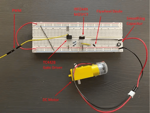 Fig 7. Buck Converter constructed and connected to DC motor
Once we have built the circuit, we can apply the power by attaching the 11.1 V battery to the appropriate buses on the breadboard. We can then measure the voltage across the motor to ensure that it is receiving the proper voltage. Figure 8 shows the oscilloscope reading of the motor voltage, which is quite noisy. This noise is common in inexpensive DC motors, and we will likely need to address this by adding a closed-loop controller and filtering capacitors in the future. However, for now, we are receiving approximately the 6 V we expected.
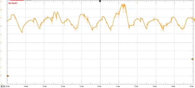 Fig 8. Voltage across real-world DC motor from buck converter
Figure 9 below shows the motor in action when it is properly powered. As you can see, we are ready to start ramping up this project! Future steps will include more control over the motor, planning the steering subsystem, and building a fully functional robot car. Along each step of the process we will continue to use the power of Altair simulation to expedite the design and implementation of our models.
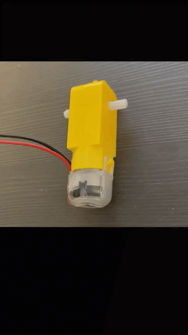
Fig 9. DC Motor powered by buck converter
Be sure to check back here often and subscribe to our YouTube channel to stay up to date on this project and other various examples, tutorials, and simulation tips. As always, be sure to reach out to us if you have any questions or comments!