
TrueInsight
Siemens/Altair Channel Partner
Menu


Using Altair WinProp to Analyze my Home Wi-Fi
In this blog, we will show you how you can optimize the design and placement of your home wi-fi network by using Altair Feko.
Many of Altair’s tools can assist engineers to design, simulate, and analyze an almost endless array of devices, constructions, and systems. However, we can use these advanced tools to complete tasks that may not seem as important or necessary in an industrial or commercial environment. One of the tools in our suite of technologies is Altair WinProp, which is part of Altair FEKO. These are part of the electromagnetic design and analysis family, and they cover a wide range of devices, including antenna design and placement. In this blog, I will only be able to scratch the surface of what is possible in WinProp, but hopefully it will shed some light on what extended applications are possible with this tool. We will walk through the process of laying out an indoor setting, placing a Wi-Fi router, and analyzing the signal performance throughout the environment. Of course, most engineers probably wouldn’t be doing this at work, but it shows the basics of what is possible with network planning in a much larger building.
To begin, I want to briefly go over what some of the tools in this specific family are and what they do. All these tools are available with the installation of Altair FEKO, the general three-dimensional electromagnetic design and simulation software, covering anything from waveguides and antennas to entire automobiles or battleships on saltwater. Then we can move to the subset of WinProp tools. WinProp is Altair’s wave propagation analysis package, and it has three tools within itself: AMan, WallMan, and ProMan. AMan allows users to design antenna array patterns; this means that you can implement a custom antenna solely with its array patterns, requiring no data on the geometry or electrical characteristics of the device. WallMan allows users to design custom three-dimensional rural and urban environments. We will take a closer look at this tool, as I used it to design the setting for this example. Finally, ProMan is the final step of this process, where custom antennas can be placed in previously designed environments, and various site parameters can be defined. This is the tool that allows us to simulate the performance of any given antenna in any 3D setting. I am sure you can already imagine the wide range of applications with just these tools alone, but today we will be walking through a project is quite unique (and frankly helpful) for me: we will be building my own home and determining if my current Wi-Fi router placement is effective!
To begin this process, I referenced a floorplan provided to me before I moved into the house. I had to make some approximations and simplifications, as the floorplan was not a true technical drawing, and not all details were present. With this in mind, we can begin constructing an approximation of my house in WallMan. Upon opening a new project, we are met with a dialog box asking for a few basic inputs, which will help us to greatly increase our design speed: Default Values for New Objects. The first section of this menu, “Geometrical Parameters for Orthogonal Drawing Mode” allows us to define how large we want to build objects, and where they should start. For example, if we wanted to draw 10 m high exterior walls, we could select the first option (Object relative to current plane), set the current plane at z=0, and the height relative to that plane as 10 m, as shown in Figure 1. We can use this logic and other options to create various subsections within these walls, such as a door that goes from 0 m to 2.5 m or a window that goes from 1 m to 2 m on the z axis.
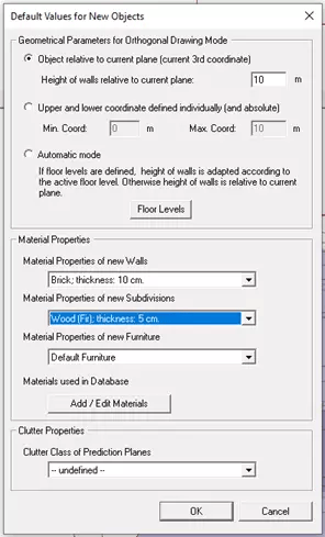 Fig. 1 Defining Default Values in WallMan
The next section of this menu is the “Material Properties,” where you can tell WallMan what these parts are made of. There is a default library of materials included in the software, but you can import your own, or define individual mediums by providing some electrical parameters, such as the ones shown in Figure 2, but we will stick to the default materials for this example.
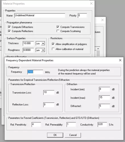
Fig. 2 Defining New Material in WallMan
I started this design by selecting the XY view of the model and adding orthogonal outer walls made of brick from 0 to 6m, assuming that each story of my 2-floor home was 3 m high. I then drew 4 outer walls creating a rectangle that was 9.5 m in the x direction and 12.5 in the y direction, as shown in Figure 3.
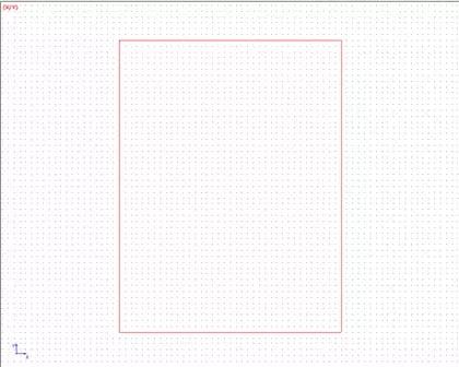
Fig. 3 Outer Wall layout in WallMan
Continuing this process, I began drawing the first-floor interior walls, making some approximations, as the floorplan I had available did not cover every dimension possible. After drawing the walls, I changed the default values for new objects to add the doors: 0 m to 2.5 m and 5 cm thick wood. After adding all the doors, I repeated the process for my windows: 1 m to 2.5 m and 2 cm glass. I even added a metal garage door on the front of the house! Much of this is an approximation for my example, but you can increase the material accuracy as much as you like in your applications. After completing the first floor, I had a resultant layout that can be seen in Figure 4.
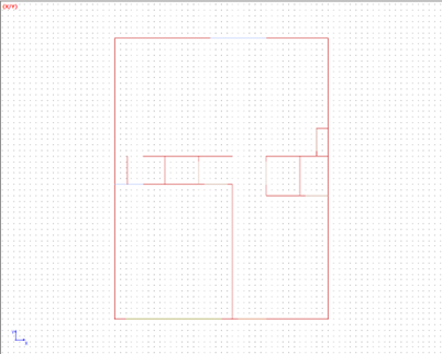
Fig. 4 First Floor layout in WallMan
I continued this process by adding a ceiling and floor in the middle of the z axis to begin creating the second story. I repeated the previously described process to layout the upstairs floorplan with interior doors and exterior windows. Additionally, there is a prebuilt staircase creation tool within the software, allowing you to define a few basic parameters (such as number of steps, step height, step depth, etc.), which will automatically generate a 3-dimensional set of stairs for you to place in the appropriate location in the model. After completing these steps, I had a final model that can be seen in Figure 5. I decided to omit the furniture in my home, but you also have the option to include desks, couches, fixtures, and more if you would like that level of accuracy. Once we are satisfied with the result, we can save the model and move along to the next piece of the project: ProMan.
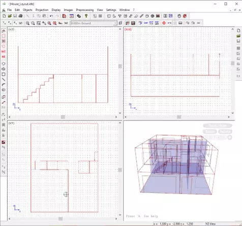
Fig. 5 Finalized WallMan Model
After importing the model, we just created into WallMan, we can add our antenna site that will represent our Wi-Fi router. I keep my router on the entertainment center beneath our television in our living room, which puts it about 0.5 m above the ground. Using the “Add Site” menu, I can click the X-Y location that I would like to place the antenna, then manually define the height (z-location). I can also manually type the X-Y coordinates if I need that level of accuracy. Next, I can define the parameters: frequency = 2400 MHz and transmission power = 0.5 W. These are generic values for a home Wi-Fi router, but you can use values from whichever antenna you happen to have. After placing and defining the router, we end up with a first-floor view seen in Figure 6.
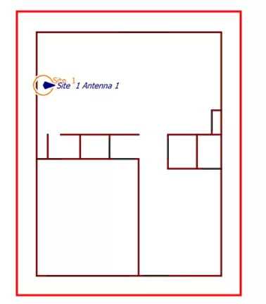
Fig. 6 Antenna/Router Placement
There are a handful of solution methods available within the tool, but I chose the 3D Ray Tracing computation by navigating to the Computation > Ray Optical Propagation Models. Lastly, solving the model is as simple as clicking Computation > Propagation: Compute All. The default results will be in the same z-axis location as the antenna, but we can look at any z-axis location of interest. Figure 7 shows the results at z=0.5, with the darkest red shading (the highest signal power) right around the router, as expected. The one area with dark blue at the bottom of the layout is right in front of the metal garage door, so it is no surprise that the signal is extremely weak there.
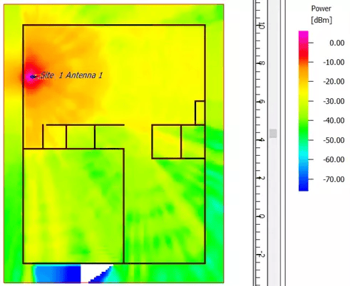
Fig. 7 First Story signal strength
Moving the z-axis to 3.5 m, which is approximately the height of my desk upstairs if we stick with the 3 m per floor assumption, we can see the strength of the Wi-Fi in the various rooms of the second floor. Figure 8 shows this information, with my bedroom and my office marked. Luckily, my bedroom is directly above the router, so there is still a strong enough signal for streaming movies on the television and browsing the internet on my phone before I go to sleep. However, you can see that the signal begins to weaken the further into my office you look. I noticed this long before completing this project, which is what inspired me to run this simulation. Ultimately, I ended up running an ethernet connection to my desk, and these results finally show that the hardwire connection was not in vain!
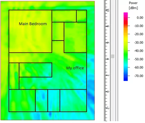
Fig. 8 Second Story signal strength
Finally, Figure 9 shows the 3-Dimensional view of the model of my home and the results upstairs in the ProMan portion of WinProp. Being able to see the model in this view can be helpful to identify which structures are possibly weakening the signal, and it can also show which parts of the house don’t interfere as much. With these tools in my hands, I could one day experiment with moving the router to different locations in the simulation to identify an optimal site for the best home-wide coverage.
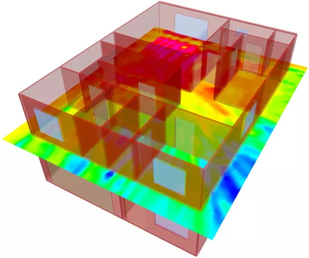
Fig. 9 3D view of home with 2D slice of results on second story
And with all that complete, we have successfully worked through some of the key features of WallMan and ProMan within Altair WinProp. Even though this was an example more “for fun,” these same ideas can be extrapolated to a much larger industrial environment for any kind of network planning. These tools can also handle outdoor environments, as well as indoor-outdoor hybrids. If you have any questions about these tools or anything else in the Altair Suite of engineering tools, don’t hesitate to reach out to us. Make sure to check back here for routine new content, and don’t forget to subscribe to our YouTube Channel for informative walkthroughs, overviews, and other videos about what Altair and TrueInsight can do for you!