
TrueInsight
Siemens/Altair Channel Partner
Menu


The Importance of Preprocessing in Simulation
Discover the critical role of preprocessing in engineering simulation with Altair HyperMesh. Our latest blog post details the importance of preprocessing.
Engineering simulation tools, specifically FEA (Finite Element Analysis) and CFD (Computational Fluid Dynamics), are critical for high-end product design and development. They enable engineers to test and validate designs before they are manufactured, which can reduce costs, improve product performance, and increase safety. This simulation process is typically executed in 3 linear steps: Preprocessing, which involves the setup of the study and mesh creation; Solving, which is the actual processing of the study; and Postprocessing, which is the visualization and reporting of the results of the study. It’s important to know that getting accurate simulation results, first and foremost, requires accurate preprocessing. In this article, we will explore the importance of accurate preprocessing within engineering simulation processes.
What is Preprocessing?
Preprocessing is the stage of the engineering simulation process where engineers create the simulation model. This involves setting up the geometry- what is being tested, applying boundary conditions – what is going to happen, and assigning material properties. You’ll often hear the term “Garbage in, Garbage out”, which essentially boils down to the notion that if you aren’t able to set up your study accurately, you will never get fully accurate results on the back end. To relate this to the preprocessing stage, it is a critical stage of the simulation process, as errors or inaccuracies introduced at this stage can propagate throughout the simulation study and lead to incorrect or inaccurate results.
Accurate simulation studies are essential for making informed decisions in the design process. Incorrect or inaccurate simulation results can lead to costly design changes, delays in time-to-market, and, in the worst cases, safety risks.
One of the biggest challenges in preprocessing is meshing. Meshing is the process of dividing the geometry into smaller elements that can be used for simulation. The quality of the mesh can have a significant impact on the accuracy of the simulation results. A poor-quality mesh can lead to incorrect or inaccurate results, while a high-quality mesh can improve the accuracy of the simulation results.
The Importance of Mesh Quality
Meshing is one of the most critical steps in setting up an engineering simulation study accurately. The quality of the mesh can have a significant impact on the accuracy of the simulation results. A poor-quality mesh can lead to incorrect or inaccurate results, a mesh that is too dense with elements will extend the processing time for your study. In comparison, a high-quality, optimized mesh can improve the accuracy of the simulation results and speed time to result.
A high-quality mesh is one that accurately represents geometry, has a sufficient volume of elements, and has the right element type for the physics being modeled. A high-quality mesh is also free from distortions, has a consistent element size, and has smooth transitions between different mesh regions. Achieving a high-quality mesh requires a robust meshing tool that can handle complex geometries and produce high-quality meshes efficiently.
The Role of Altair HyperMesh in Accurate Simulation Studies
Altair HyperMesh is a powerful meshing tool that can help achieve accuracy in engineering simulation studies. HyperMesh offers a range of features that enable engineers to model physics accurately and generate high-quality meshes efficiently.
Advanced Geometry Cleanup Tools. This includes tools for repairing CAD geometry, removing small features, and simplifying complex geometries. This helps ensure that the geometry used in the simulation model accurately represents the physical problem being studied. This can be particularly useful when working with CAD models that have been imported from other software packages or when dealing with complex geometries that can be difficult to mesh.
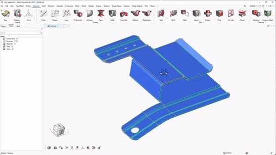
Fig 1: HyperMesh Geometry Ribbon Menu
Advanced Mesh Controls. HyperMesh offers a range of meshing options, including tetrahedral, hexahedral, and hybrid meshing. This enables engineers to choose the right mesh type for the physics being modeled and generate high-quality meshes efficiently. For example, tetrahedral meshing is often used for complex geometries, while hexahedral meshing is ideal for simple geometries. Hybrid meshing can be used when a combination of tetrahedral and hexahedral elements is required.
HyperMesh also includes tools for automatic mesh refinement and optimization, helping engineers achieve the optimal mesh quality for accurate simulation results. Automated mesh controls are used to generate a mesh automatically based on a set of predefined criteria. This is particularly useful when dealing with complex geometries, where manually defining mesh controls can be time-consuming and error-prone.
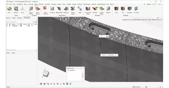
Fig 2: Mixed Mesh in Altair HyperMesh
Intuitive, Customizable User Interface. The ease of use of HyperMesh is amongst the leading reasons why engineers switch from other tools. The interface is designed to be intuitive and easy to navigate, with clear menus and icons that make it easy to access the software's features.
HyperMesh also offers a customizable user interface, which can be particularly useful for engineering teams with specific workflow requirements. By customizing the user interface, engineers can streamline their workflow and improve productivity. For example, engineers can create custom menus or toolbars that include frequently used commands or macros. This can help engineers work more efficiently and reduce the time required to perform preprocessing tasks.
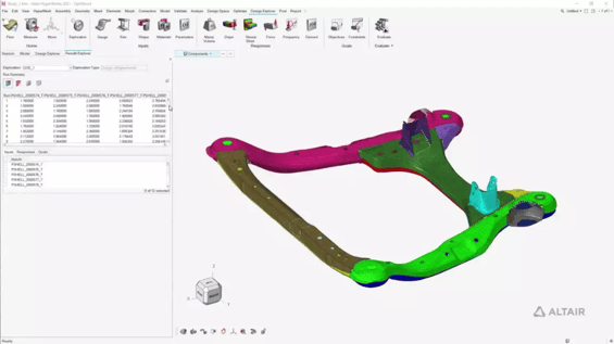
Fig 3: HyperWorks GUI Design Explorer Ribbon
Integration with Other Tools. HyperMesh is both CAD (Computer Aided Design) and Solver agnostic. This means it can import files from most major CAD tools and can export to all the most popular solver decks. For Altair customers, HyperMesh integrates with other Altair software products, such as OptiStruct, Radioss and HyperWorks CFD. This enables engineers to use HyperMesh to create simulation models that can be easily integrated into other simulation workflows, such as optimization or structural analysis.
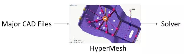
Fig 4: HyperMesh workflow representation
HyperMesh In Action
To illustrate the importance of accurate simulation studies, let's look at a few case studies.
Accuride worked with Altair to develop an automated solution that cuts down the time, teams need to spend on prepping surfaces and elements. The automated HyperWorks solution enabled the team to run a complete analysis and deliver reliable results in a shorter timeframe.
What they do: A leading global manufacturer and supplier of high-quality, innovative products for the transportation industry.
Their Challenge: When developing truck and passenger wheels, creating a solid hexahedral mesh is one of the most time-consuming tasks that needs to be completed.
Results of using HyperMesh: HyperMesh automated the Hexa-Mesh creation of truck and passenger car wheels based on provided user inputs like element size, the density of the solid mesh and more. The new automated workflow reduced a process that used to take seven hours of manual work to a mere seven minutes, which is estimated to save Accuride up to 765 hours per year.
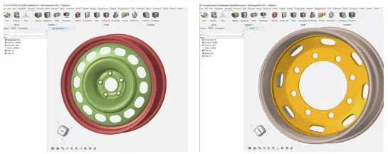
Fig 5: LEFT: Accuride engineers were able to mesh complex parts, like the model with over 160k elements shown here, in minutes. RIGHT: Several FE modeling parameters – including element size, quality, and meshing techniques – can be controlled within the HyperWorks workflow
EVR Motors
EVR took advantage of Altair’s Electric Motor simulation suite of tools, Altair Flux, Altair HyperWorks, Altair HyperMesh and Altair SimLab to optimize a new e-motor design.
What they do: Designs and develops cost-effective radial flux Permanent Magnet (PM) electric machines for a range of power conversion applications such as renewable energies and vehicle electrification.
Their Challenge: EVR chose to invent a new topology and develop a completely new type of motor for the electrical vehicle industry called the Trapezoid Stator RFPM topology, rather than try to optimize existing technology as other companies had been doing.
Results of using HyperMesh: EVR has already achieved a simulation accuracy of about 90%, but they’re aiming to improve this to even higher accuracy of 95-96%. Through simulation, EVR developed and tested its new patented motor, which is half the size of some of the industry’s best e-motors.
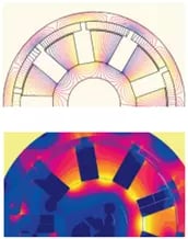
Fig 6: TOP: 2D Magnetic flux isovalues in the trapezoid Stator RFPM motor
BOTTOM: 2D Magnetic flux density in the trapezoid Stator RFPM motor
To summarize, Altair HyperMesh is a powerful engineering simulation tool that is designed to be easy to use for engineers of all skill levels. Its user-friendly interface, advanced geometry cleanup tools, advanced mesh controls and integration with other Altair software products make it a versatile and efficient tool for preprocessing in engineering simulations. To learn more or try it for yourself, contact us today!