
TrueInsight
Siemens/Altair Channel Partner
Menu



How Simulation Users Can Get More from Siemens CAD Tools Like Solid Edge and NX
Simcenter Simsolid works directly on native Siemens Solid Edge and NX geometry, no meshing, no geometry cleanup. Find out how.
For years, engineers have had to choose between great CAD tools and great simulation tools. With Siemens and Altair now part of the same portfolio, that trade-off is disappearing. If you design in Siemens Solid Edge or Siemens NX, and you want to run structural simulation without rebuilding your model or waiting for a meshing specialist, Simcenter Simsolid was built for exactly that situation. This post walks through how that connection works in practice, covering the geometry handoff, the simulation workflow, and where the broader Altair simulation portfolio (now Simcenter) adds value for teams already working in Siemens CAD environments.
Why CAD-to-Simulation Handoff Has Always Been Painful
Structural simulation has traditionally required a purpose-built model that is separate from the CAD model. A designer builds a detailed assembly in Solid Edge or NX, with fasteners, thin walls, complex fillets, and real-world geometry and then a simulation engineer receives it and spends significant time simplifying it. Fillets are removed. Fasteners are replaced with rigid connections. Thin sheet metal parts are converted to mid-surface shell representations. Small features that would create mesh quality problems are defeatured. That process can take hours or days depending on the complexity of the assembly, and it must be repeated each time the design changes.
The mesh itself is another step. Once the geometry is idealized, the analyst builds a finite element mesh, a grid of elements that discretizes the part so the solver can compute stress and displacement at each node. Mesh quality directly affects result accuracy, which means this step requires expertise and careful review. For many design teams, this bottleneck limits how often they can run simulation and pushes analysis to the end of the design process, when changes are costly.
What Altair Simsolid Changes for Siemens CAD Users
Simcenter Simsolid removes both of those steps. It operates directly on native CAD geometry using a meshless finite element method based on adaptive polynomial functions. Engineers import their assembly as-is, with all the real geometry intact and start setting up the simulation immediately. No geometry cleanup, no mid-surfacing, no mesh generation.
For teams working in Solid Edge, this is a meaningful shift. A designer can export a Solid Edge assembly as a STEP, Parasolid, or JT file and open it directly in Simsolid within minutes. Contacts between parts are detected automatically, including welded connections, bolted joints, and sliding interfaces. Material properties and load cases are applied interactively. The solver runs in minutes even for large assemblies with hundreds of parts, and results (displacement, von Mises stress, safety factor, reaction forces) are available immediately in an interactive post-processing environment.
Simsolid also reads Solid Edge native files directly, meaning designers do not need to go through a translation step. For NX users, Simsolid supports NX native file formats as well, making the handoff straightforward whether the geometry was built in NX or Solid Edge. The software handles the file translation internally, which eliminates version mismatches and reduces the risk of data loss during format conversion.
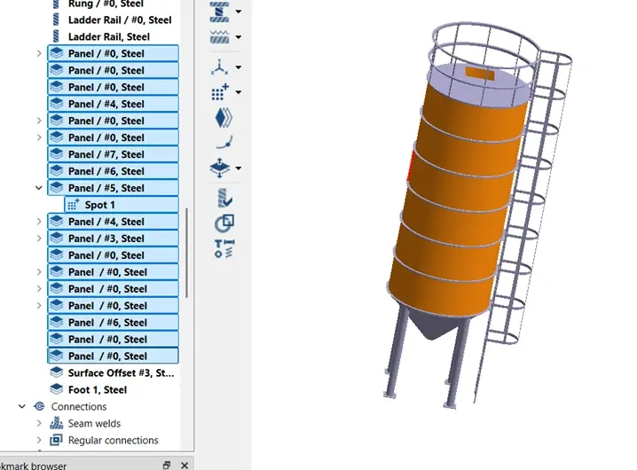
Fig 1: Simsolid model with material data
Simsolid Inside Solid Edge: The Embedded Experience
The most direct integration between these tools is the Simsolid experience that is embedded inside Solid Edge. Siemens has made Simsolid available as a module that runs within the Solid Edge environment, which means designers never leave the application they are already working in. They can apply loads, define boundary conditions, run the analysis, and review results without switching tools.
This is particularly valuable for design engineers who are not simulation specialists. The embedded workflow presents a simplified setup experience that guides the user through material selection, load and constraint definition, and results review. The full complexity of traditional FEA is hidden behind a streamlined interface, but the solver underneath is the same technology that structural analysts use in the standalone Simsolid application.
For an engineer designing a weldment, a bracket assembly, or a sheet metal enclosure in Solid Edge, this means they can answer basic structural questions: Is this part going to bend too much under load? Where is the highest stress concentration? Does this design pass a safety factor requirement? without sending the model to an FEA team and waiting for results. Those questions can now be answered in the same session where the design decision is being made.
The benefit compounds over time. When simulation is easy to access, engineers run it more often. They test more design alternatives. They find problems earlier, when changes are cheap. The result is fewer surprises at the validation stage and a higher-confidence design entering detailed engineering.
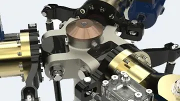
Fig 2: Assembly rendering from Solid Edge
NX and Simsolid: Simulation at the Speed of Design
Siemens NX is used by some of the most demanding engineering programs in the world, aerospace structures, automotive body-in-white, industrial machinery, and defense systems. These programs typically have dedicated FEA teams, established solver workflows, and long-standing simulation processes. Simsolid fits into those environments not by replacing the detailed analysis workflow, but by enabling early-stage design assessment before the formal analysis begins.
In a typical NX-based program, concept geometry exists weeks or months before a fully validated simulation model is ready. During that period, engineers are making design decisions like sizing members, selecting cross-sections, positioning reinforcements, without much quantitative structural data. Simsolid fills that gap. An NX model that is still under development can be exported and run through Simsolid to get directional answers about load paths, relative stiffness, and stress distribution. Those answers inform design decisions without waiting for the full FEA model to be built.
NX also includes simulation capabilities through Siemens Simcenter, and for detailed analysis at the validation stage, those tools are the right choice. Simsolid is complementary: it runs faster, accepts messier geometry, and requires far less specialist time to operate. The two tools work best when used at different points in the design cycle: Simsolid early and often, Simcenter for detailed, signoff-level structural analysis.
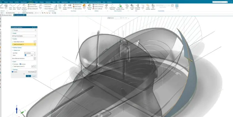
Fig 3: NX Model with advanced surfacing
Assembly-Level Simulation: Where Simsolid Excels
One of the clearest practical advantages of Simsolid for Solid Edge and NX users is its handling of large assemblies. Traditional FEA tools require significant effort to build a simulation-ready model of an assembly. Each part needs appropriate meshing, contacts need to be defined carefully, and the total element count grows quickly with the number of parts. For an assembly with 50 or 100 parts, the model preparation time alone can take several days.
Simsolid was designed to handle complex assemblies directly. Users have reported running studies on assemblies with several hundred parts in under an hour from file import to results on standard engineering workstations, without HPC infrastructure. This includes automatic contact detection for bolted joints, weld seams, and interference fits, which removes one of the most tedious steps in traditional assembly FEA preparation.
For Solid Edge users building equipment frames, enclosures, and multi-component mechanical assemblies, this means full-system structural assessment is available at any point in the design process. For NX users working on larger programs, it means directional structural data can be generated from development-stage geometry without committing to a full pre-processing workflow.
Connecting to the Broader Altair Simulation Portfolio (Simcenter)
Simsolid is where most Solid Edge and NX users will start, but it is part of a larger Altair simulation portfolio that can support the full engineering lifecycle. Once initial concepts are validated in Simsolid, teams often move geometry into more specialized Altair tools for deeper analysis.
Simcenter Optistruct is the logical next step for teams that want to optimize their designs, not just validate them. OptiStruct's topology optimization capability can take a design space, the envelope within which a part can exist and determine the most structurally efficient material distribution for a given set of loads and constraints. For Solid Edge users designing custom brackets, housings, or structural members, OptiStruct can suggest a lightweight geometry that the designer then refines in Solid Edge before the next Simsolid check.
Simcenter HyperMesh is the pre-processing tool for teams that need to move from concept analysis to detailed FEA. After a design has been roughed out using Simsolid, the final geometry from NX or Solid Edge can be brought into HyperMesh for a full, high-fidelity finite element model. HyperMesh supports both Altair solvers, OptiStruct and Radioss and Siemens Nastran, so it integrates naturally into programs that already have established Nastran workflows.
Simcenter Inspire is another tool worth mentioning for Solid Edge users in particular. Inspire is a concept design environment that combines structural optimization and geometry creation in a single interface. While Solid Edge is the right tool for detailed design and manufacturing drawings, Inspire is useful at the very start of a project when the design hasn't been defined yet. Engineers can define loads and constraints in Inspire, run a topology optimization, and use the resulting organic geometry as the starting point for a detailed model in Solid Edge.
Common Pitfalls When Connecting CAD and Simulation Workflows
Moving between CAD and simulation tools is straightforward in principle but has practical details worth knowing. Here are the most common issues teams encounter when connecting Solid Edge or NX to Altair simulation tools, and how to avoid them.
File format mismatches. Simsolid reads Parasolid, STEP, IGES, JT, and native Solid Edge and NX formats. Using Parasolid (.x_t or .x_b) is generally the most reliable choice for preserving geometry fidelity because both Solid Edge and NX use Parasolid as their underlying geometry kernel. STEP is a safe fallback but can occasionally introduce conversion artifacts in complex surfaces.
Assembly structure and contacts. Simsolid detects contacts automatically based on proximity and overlap, but the defaults may not always match the physical intent. For bolted assemblies, it is worth reviewing the contact definitions and confirming that fastener connections are represented correctly — either as bonded, sliding, or separation-allowed contacts, depending on what the design actually does. Spending a few minutes on contact review before running the solver prevents misleading results.
Unit consistency. Solid Edge and NX both support multiple unit systems, and Simsolid needs to match the units used in the exported file. Always confirm the unit system at import and check that material property values like density, modulus, yield strength are entered in consistent units. A modulus entered in MPa when the model is in millimeters will give correct results; the same value entered as GPa will produce incorrect stiffness by a factor of 1,000.
Material definitions. NX and Solid Edge both have material libraries, but those material assignments do not transfer automatically to Simsolid. Material properties need to be reassigned in Simsolid at import. Simsolid has a built-in material library for common metals and plastics, but for proprietary or specialized materials, the properties need to be entered manually.
Result interpretation. Simsolid results are directional, not certification-grade. For early design decisions, the stress and displacement results are highly useful. For final validation and sign-off, it is worth running the geometry through a full FEA model in HyperMesh or Simcenter. Simsolid is most effective when it is used to guide design direction and eliminate poor options early, with traditional FEA used for final confirmation.
A Practical Example: Bracket Assembly in Solid Edge and Simsolid
To make this concrete, consider a team designing a welded steel equipment bracket in Solid Edge. The bracket has eight components: Two main structural channels, four gussets, and two mounting plates connected by fillet welds. The design team wants to know whether the bracket will meet a 3:1 safety factor under a defined load case before they finalize the weld sizes and material thickness.
In a traditional workflow, the team would send the Solid Edge assembly to an FEA specialist, who would idealize the geometry, build shell elements for the plate components, define weld connections, mesh the assembly, set up the load and boundary conditions, run the solver, and post-process results. That process might take two to four days for a first result, and if the design changes, the process restarts.
With Simsolid, the designer exports the Solid Edge assembly as a Parasolid file. Simsolid opens it in under a minute, detects the part contacts, and presents an assembly view with all eight components. The designer assigns steel from the material library, applies a fixed boundary condition at the mounting holes, applies the load at the designated pick point, and runs the analysis. Simsolid returns displacement and von Mises stress results in three to five minutes. The designer reviews the safety factor contour, identifies that one gusset is over-stressed, adjusts the thickness in Solid Edge, exports the updated file, and runs the check again. The full cycle, design change, export, analysis, review takes less than 30 minutes.
When the design stabilizes and the team is ready for final validation, the Solid Edge geometry goes to HyperMesh for a detailed shell mesh with explicit weld elements, and the OptiStruct solver is used for the signoff analysis. The Simsolid results from the iteration phase gave the team confidence that the design entering detailed analysis was already well-tuned, reducing the number of analysis-driven redesign cycles at that stage.
Managing the Combined Toolkit with TrueInsight
As an Altair and Siemens channel partner, TrueInsight supports engineering teams that are working across both toolsets. Whether your team is purely in Solid Edge and looking to add simulation capability, or you are an Altair simulation user looking to understand what the Siemens CAD tools can offer, we can help you map out the right configuration for your workflow.
We help organizations with software licensing, initial setup, workflow integration, and training on the connection between Simsolid and Solid Edge or NX. We also support teams that want to build a connected simulation process that spans Simsolid for early concept checking, HyperMesh for model preparation, OptiStruct for optimization, and Simcenter for validation. If you want to talk through how these tools would fit your specific design and analysis workflow, reach out to us at TrueInsight and we can set up a conversation.