TrueInsight
Siemens/Altair Channel Partner
Menu


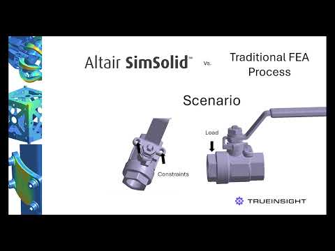
Comparing Traditional FEA and Altair SimSolid
In this video we look at Altair SimSolid, a meshless simulation solution, and compare it to a traditional FEA process.
The process of running a simulation using traditional FEA methods comes with inherent challenges that, at times, can require the user to simplify complex geometries before creating a mesh. These steps can be time consuming but also reduce accuracy. This post will compare how a designer can run a quick analysis using both traditional FEA process and Altair SimSolid, which requires no geometry simplification or mesh creation.
Understanding Traditional FEA Processes in Design
Why Create a Mesh?
FEA breaks complex shapes into small pieces called elements. These elements form a mesh. Each element is governed by mathematical equations that approximate the behavior of the real material or structure. The more elements you have (i.e., a finer mesh), the more accurate your solution can be, but it also demands more computational resources.
Why Simplify the Design Before Meshing?
- Reduce Computational Load
- Complex models with detailed features like small fillets, holes, threads, or logos, can lead to many unnecessary mesh elements. This increases the time and memory needed to run a simulation. By removing or simplifying these non-critical details, you can reduce mesh density where it doesn’t impact the accuracy of results, improving simulation speed and stability.
- Avoid Poor-Quality Meshes
- Complex or very thin features often lead to high aspect ratio elements or distorted elements, which negatively affect solver performance and result accuracy. Simplifying the model geometry can help produce a cleaner, higher-quality mesh, making the simulation more robust.
Altair SimSolid
Instead of breaking the model into discretized elements, SimSolid analyzes the entire geometry as it is, directly from the CAD file. It does this using advanced math that divides the model into arbitrary geometrical shapes based on the geometry facets it imports (like faces or volumes) and then uses equations called basis functions to estimate how each region behaves under loads.
Additionally, it’s accuracy has been verified by NAFEMS, making it a reliable tool for real-world engineering. In many cases, designers will use SimSolid during the design phase, ensuring the most optimized design before sending it on for final analysis.
Side-by-Side Comparison: Traditional FEA vs. Altair SimSolid
For this comparison we are going to use a simple example. As seen in the image below, we will constrain the model in the mounting holes indicated by red arrows, and I will apply a load on the end, blue arrow. I am intentionally using a simple example to make it easier to understand the steps, but most real-world scenarios will be more complex, which would make the SimSolid process even more valuable.
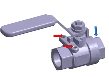
Fig 1: Example model with constraints and load
Setup Time
In the traditional FEA process, I started by isolating the parts of my assembly that are needed for the analysis. I then removed any unnecessary fillets, since those aren’t in critical locations, and can lead to additional mesh elements being created. After that, I created the mesh, as a uniform mesh across the entire model before starting to set up my study.
For the setup I applied constraints at the mounting holes, applied the load of 300 Mpa of pressure, then ran my solver. This entire setup process went quickly but took about 1 Minute and 55 seconds.
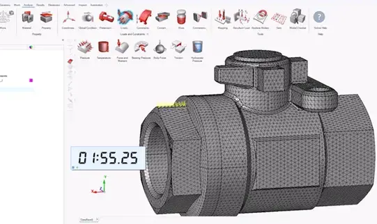
Fig 2: Traditional FEA model ready for solve
With SimSolid, I bypass the steps of preparing my model for my study and move right into applying the constraints and loads, identical to the FEA process. Because I was able to move right into the study, I was able to get the model ready to solve very quickly, about 33 seconds.
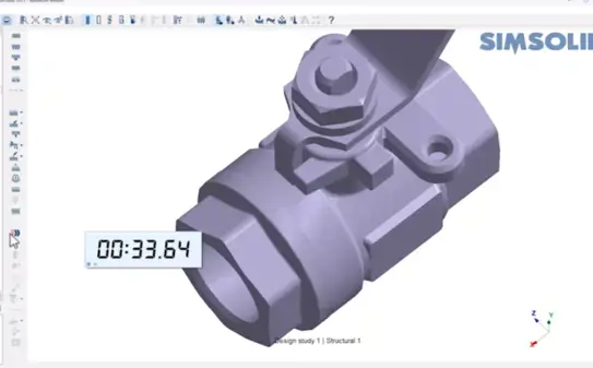
Fig 3: SimSolid model ready for solve
Solve Time
Because the Traditional FEA process must solve the mathematical solution for each node on each element of my model, it takes a little longer than the meshless counterpart, but even still this analysis solved in about 1 Minute and 10 seconds.
SimSolid doesn’t use a mesh to find the impact of the load, instead it uses a series of approximations and adaptive refinement to quickly solve the analysis and in this example, it took only 4 seconds.
Accuracy and Validation
The question we get asked the most with regards to SimSolid is “How accurate is SimSolid?”. As mentioned before, Altair SimSolid has been included in NAFEMS accreditation processes, which prove it maintains comparable accuracy to most FEA solutions in most scenarios. In our comparison, SimSolid predicted a stress of 3.55 MPa, while traditional FEA measured 3.46 Mpa. That’s less than 3% difference, which typically falls in range for most designers making quick decisions during the design cycle.
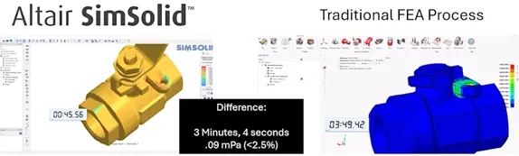
Fig 4: Results comparison with time stamps
Best SimSolid Applications
While SimSolid is a powerful simulation tool regardless of the application, here are some of the most common uses we have seen with our customers:
- Quick Design Changes: The ease of use, rapid study setup and short solve time is ideal for those needing to get quick answers to optimize designs before final analysis.
- Large Assemblies: Large or complex assemblies typically require a lot of part defeaturing, component merging and historically require a large amount of computing power and time. With SimSolid, users bypass these steps to get quick answers.
- CAD-Heavy Workflows: SimSolid works directly on native CAD files without the need to heal or simplify, making it a seamless step into any current workflow.
If you want to learn more or discuss the potential impact of SimSolid on your workflow, contact us!