TrueInsight
Siemens/Altair Channel Partner
Menu


New Electromagnetic Simulation Features in Altair SimSolid 2026
New to Altair SimSolid 2026 users can now run electromagnetic simulation without the need to create a mesh!
Altair SimSolid 2026 brings a major change to how engineers work. In the past, this software focused on structural and thermal simulation. Now, it includes electromagnetic simulation. This is the first time the software can handle these kinds of solutions. You can now look at electric fields and currents on your CAD models. The best part is that it uses the same technology that makes SimSolid so useful, users don’t have to create a traditional mesh or simplify geometry. This allows them to move straight into setting up their study, saving a lot of time and error-prone steps.
The Power of Meshless Electromagnetic Simulation
Traditional simulation tools, including electromagnetic simulation tools, require a mesh. This mesh is a grid of shapes that dissects a part, with each corner acting as a node for measurement. As users know, creating this mesh can take a long time and be detail-oriented which can lead to small user errors. The results of the simulation are only as accurate as the mesh that’s created.
As structural or thermal users already know, SimSolid does things differently: It operates directly on the native CAD geometry using advanced mathematical techniques that approximate the solution over the entire model. For the geometry simplification, this means engineers can skip time-consuming steps like defeaturing, mid-surfacing, or mesh refinement, and go straight into the study setup. The elimination of these two steps can drastically speed up the process and cut simulation times from hours to minutes. The 2026 release focuses on two main types of electromagnetic analysis S-Parameters and Modal Analysis.
S-Parameters
S-parameters help you understand signal quality. You can see how much signal is transmitted, absorbed or reflected back. Essentially this gives you a high-level picture of the operating range (a.k.a bandwidth) for your model. These are typically used with applications like RF filtering, antenna design or antenna matching, connectors and cables or microwave components.
Setting up an S-Parameters Analysis in SimSolid
To start setting up an electromagnetic simulation in SimSolid, I am going to create a new material and label it “Air”. I do this to define the entire device as air first. I can later define faces regions as other materials, such as conductors, but it will keep the interior and open faces defined as air.
I do this by finding the Settings menu in the ribbon> Material Database> Right click Generic Materials and Add Material. You can then add the parameters and hit Save.
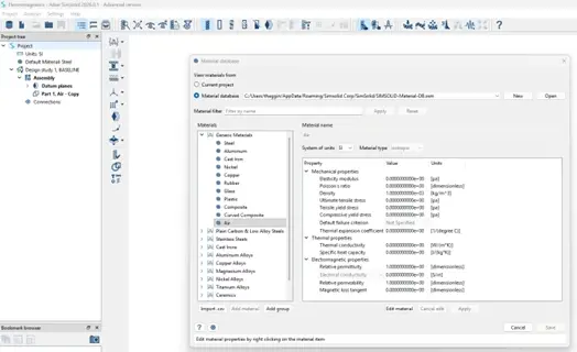
Fig 1: Material Database location and options
You will need to apply this material by selecting the Assembly from the Project Tree on the right-hand side, choosing Find/Review Materials, then applying Air as the material to All Parts.
Next you will start your study setup. New in the 2026 release, you will see the new Electromagnetic symbol in the ribbon, with a drop-down menu with options to choose S-Parameters or Modal Electromagnetics options. Choose S-Parameters.

Fig 2: Electromagnetic symbol from main ribbon
It will then give you a dialog menu to add your S-Parameters frequency span. For my example I am going to add 14GHz as my lower limit, and 16GHz as my upper limit and add 3 frequencies and select OK. This is basically saying add 3 frequencies at 14, 15 and 16GHz.
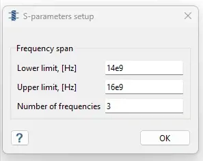
Fig 3: S-Parameters setup options
Next, we will set the waveguide port conditions. Click on the S-Parameters from your Project Tree and choose the Waveguide Port symbol from the side menu.
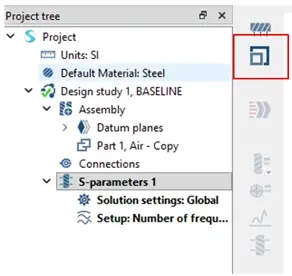
Fig 4: Waveguide Support symbol location
In the dialog menu that pops up, choose the faces you want to be open, so the In and Out ports. For my example, I chose the wattage as 1W and hit apply.
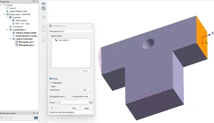
Fig 5: Faces selected as waveguide ports
Next, I will define my conductor by selecting the Perfect Electric Conductor icon from the side menu, as seen in the image below.
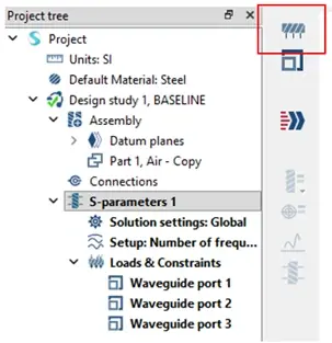
Fig 6: Perfect Electric Conductor symbol location
In the dialog menu you will need to select the faces that will act as a conductor in your simulation, so for my example, I chose the remaining faces and select OK.
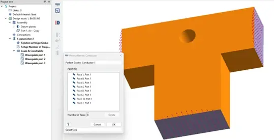
Fig 7: Faces selected as conductor
Then I am ready to run the simulation, by selecting the double arrow symbol from the side menu. For me this study took a couple of minutes to finish, then I can start looking at the results. Clicking on the results symbol shows you the options for the types of results you can get from this study like: Electric Field, Electric Flux Density, Magnetic Field and Magnetic Field Density.
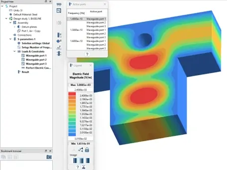
Fig 8: Electric Field results
Modal Analysis
Now, I can move onto the Modal Analysis. Modal analysis shows how waves move as "modes" through a system. This helps you find the natural ways electricity flows through a part. It is useful for understanding the range of frequencies a device can handle.
To set this study up, go back to the main ribbon and select the Electromagnetic symbol, then Modal electromagnetics. This will pop up a menu asking you to define the number of modes. For my example, I will add 9 modes.
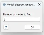
Fig 9: Modal electromagnetics menu
Then, the only parameters I need to define is the conductor, by selecting the Perfect Electric Conductor symbol. And for this example, I chose the entire model, so all the open faces.
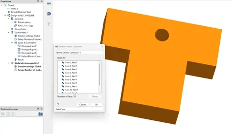
Fig 10: Faces selected as conductors for modal
Then I can run the study, which again takes only a few minutes to finish. Then under the results I have the same visualization options, but they are separated by the number of modes I selected up front.
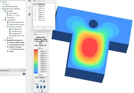
Fig 11: Electric Field results by Mode
Hopefully this has helped you with how to set up the simple electromagnetic studies using SimSolid. If you have any further questions or want to discuss your application, reach out to us.