
TrueInsight
Siemens/Altair Channel Partner
Menu


How Tight Should Your Connection Tolerances Be in Simcenter Simsolid?
In this post we show how to take advantage of the ability to work with imperfect geometry and optimize tolerances/gaps.
Simcenter Simsolid is a structural simulation tool that works directly on CAD geometry without the need for meshing. One of its biggest advantages is that it is tolerant of imperfect geometry, including small gaps and overlaps between parts.
That said, connection tolerances still matter in Simcenter SimSolid, not for meshing, but for connection detection. In this blog, we will look at what connection tolerances control in Simcenter SimSolid and what happens when they are set incorrectly, and how to choose the right values for your model!
What Geometry Tolerances Control in Simcenter Simsolid
When you import an assembly into Simcenter Simsolid, you are prompted to automatically detect connections between parts (Figure 1). Simcenter Simsolid uses two tolerance values to determine whether surfaces on adjacent parts are close enough to be connected:
- Gap tolerance — the maximum distance between two surfaces that will be treated in contact. Any gap smaller than this value will be bridged and a connection will be created.
- Penetration tolerance — the maximum overlap between two surfaces that Simcenter SimSolid will accept as a valid contact interface.
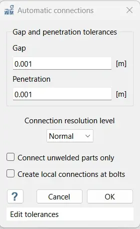
Figure 1: Gap and Penetration Tolerances Menu in Simcenter Simsolid
What Happens When Tolerances Are Too Loose or Too Tight
If your tolerances are too large:
- Parts that should not be connected may get joined together. This is common with thin-walled parts, stacked components, or anything with a small physical clearance.
- The stiffness of your model can be artificially inflated, leading to inaccurate results near connection boundaries.
- Stress results near those boundaries may be distorted.
If your tolerances are too small:
- Parts that should be connected may not be detected as touching, especially if there are small gaps in CAD.
- You may see unexpected rigid body modes when you run your analysis. When you run your analysis, it will be flagged as an under-constrained part.
- You will need to add connections manually, which increases setup time.
I would recommend you keep both gap and penetration tolerances as small as possible while still connecting your parts. A good starting point for SI units is 1 to 2 mm for gap tolerance and roughly half that for penetration tolerance. In IPS units, that is approximately 0.03 to 0.06 inches and 0.015 to 0.03 inches respectively.
How to Choose the Right Tolerance for Your Model
- Specify a Default Gap and Penetration Tolerance
Immediately after you import a file to Simcenter Simsolid you will be prompted to key in the connections. As was discussed above, use what I recommend as a default starting point size. In step two we can review the connections that are found and if there are any issues specifically with the gap or penetration settings.
- Run the Check Geometry Defects Tool Second
After running the automatic connections first, we can use the check connections tool to see the gaps and penetrations in the model. The check connections tool will identify gaps, overlaps, and non-manifold faces in your assembly. The results will give you a clearer picture of what your tolerance values need to be, as shown in Figure 2.
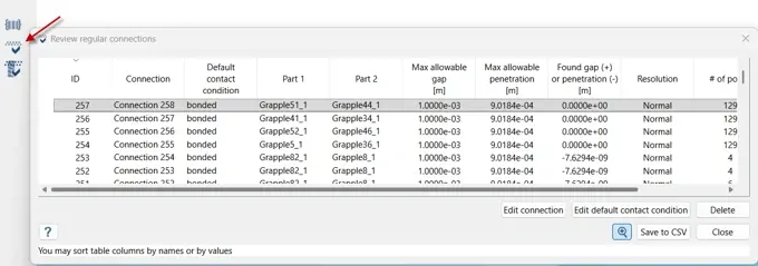
Figure 2: Checking Gap and Penetration Issues in Simcenter Simsolid
- Keep penetration tolerance proportional to your actual overlaps
Large penetration tolerances can increase the stiffness of a joint and reduce the accuracy of stress results near the connection boundary. Only use a penetration tolerance large enough to cover the maximum overlap in your model. If overlaps are significant, it is better to resolve them in your CAD tool before running your Simcenter SimSolid project!
- Do not merge parts
This is a common habit carried over from traditional FEA workflows. In Simcenter Simsolid, merging parts reduces accuracy and slows down the solution. Always keep parts as separate entities and let Simcenter SimSolid handle the interfaces through connection detection.
When the Default Settings Are Fine
For most well-built CAD assemblies: brackets, enclosures, structural weldments, Simcenter Simsolid's automatic tolerance selection and connection detection will be adequate without any changes. The solver is designed to handle minor geometry imperfections natively.
Where you need to pay closer attention is at the extremes: very large assemblies with fine detail, geometry imported from multiple CAD sources, or precision parts where even small inaccuracies in contact stiffness would affect your results.
If you do encounter unexpected rigid body modes after running connection detection, that is a signal that a connection was not found. Adjusting the gap tolerance or adding a manual connection will typically resolve this quickly!
Geometry tolerance in Simcenter Simsolid is not the same as geometry cleanup in traditional FEA. You are not patching a model so it can be meshed, you are telling the solver how contacts will be assessed in assemblies. The right approach is to start with the defaults, run the geometry defect check, review your automatic connections, and adjust from there. For most assemblies, this is a straightforward process that takes only a few minutes compared to hours in traditional FEA.
To learn more about Simcenter Simsolid or any other Siemens product, please contact us here at TrueInsight!