
TrueInsight
Siemens/Altair Channel Partner
Menu


Parametric Geometry in Simcenter FEKO: World Cup Stadiums
Check out how you can create parametric geometry in Simcenter Feko for electromagnetic analysis!
With the World Cup beginning soon, fans of soccer (or football, as most of the world knows it) will soon turn their attention to the various pitches within the North American venues and stadiums. The construction of these stadiums required teams of dedicated engineers to commit time and effort. Of all the factors to consider in the design process, we will focus on the electromagnetic analysis of these stadiums using Simcenter FEKO. After all, how many times have you been at a sporting event and been frustrated at the lack of cellular reception? FEKO is the tool that allows us to examine and predict these types of scenarios.

Fig 1. World Cup Trophy in a venue/stadium.
Simcenter FEKO is a versatile high-frequency electromagnetic (EM) design and simulation software. Within FEKO, users can create or import custom geometry, apply EM properties, solve, and post-process. In this blog, we’ll look at how you can use FEKO’s intuitive CAD design features to create a parametric model, allowing for easy physical changes based on minor variable updates. We’ll demonstrate this by creating the geometry for a simple stadium that might be similar to one used in the World Cup.
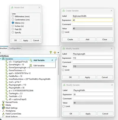
Fig 2. Initial definition of variables.
To start, we’ll set our model units to Meters, as shown above in Figure 2, and begin defining our parametric values; in FEKO, these are unsurprisingly referred to as variables. Figure 1 also shows the Variable Browser as well as a few menus where specific variables are being created or edited. For instance, we’ll need to define the length and width of the pitch, which are set as PlayingLength and PlayingWidth, respectively. Variables can be created and edited in a variety of ways in FEKO, such as right-clicking the Variable Brower heading or double-clicking an existing variable. Other values can be set here, too, such as the buffer around the pitch before the seating area starts, the size of the seating structures, or the thickness of the dome over the stadium.
For this demonstration, we’ll keep it simple and define the playing area as an ellipse based on the size parameters we defined earlier. The result of this can be seen below in Figure 3. To add the seating, we will generalize smaller tiers of the stadium with predetermined widths and heights, which will be shown shortly. This keeps the design simple for our use case, but feel free to add more detail if needed or desired
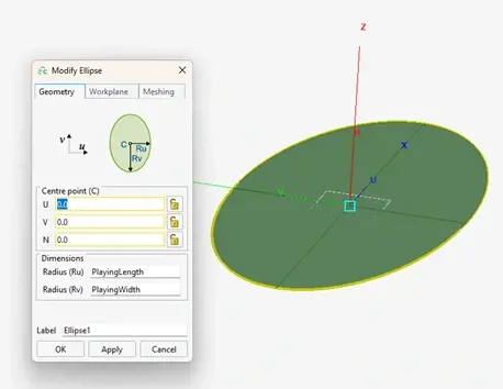
Fig 3. Creating pitch by approximating it as ellipse.
To create the first tier, we will follow the process outlined in Figure 4 below: duplicate the original ellipse (by right-clicking and choosing “Copy (Duplicate)”), create a new and slightly larger overlapping ellipse using the defined tier width, generate a Boolean subtraction to leave the outer “ring” of the larger ellipse, and then sweep the “ring” to create the first 3D row.
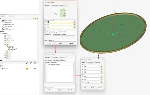
Fig 4. Process of creating first tier.
To add a new tier, simply repeat the process and adjust for the even larger ring (add 2 times the TierWidth instead of 1). Figure 5 below shows the repetition of this process to generate a new layer.
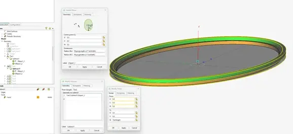
Fig 5. Process of creating second tier.
After confirming, we can start to see the stadium shape taking form in Figure 6!
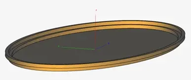
Fig 6. Completion of first two tiers.
For this example, I chose to create 10 of these tiers for the “lower bowl” of my stadium, which yielded the geometry shown in Figure 7.
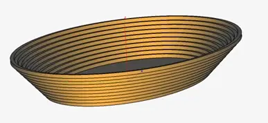
Fig 7. Completion of “lower bowl.”
Now I want to add an “upper bowl.” Again, I can use the duplicate feature of FEKO to my advantage, but it doesn’t stop there: I will use the Copy and Translate operator to move a copy of the first tier to the top of the structure, using one of our variables, as seen in Figure 8.
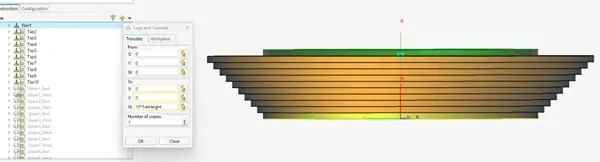
Fig 8. Duplicating first tier to begin “upper bowl.”
Figures 9 and 10 showcase how we can cut this specific geometry along a specific plan and then translate each piece, again using multiples of our previously created parameters.
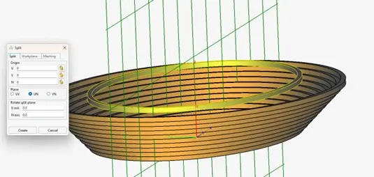
Fig 9. Using Split on first layer of “upper bowl.”
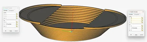
Fig 10. First layer of “upper bowl” added using Translate.
After repeating these steps a few more times, Figure 11 shows us the complete “upper” and “lower bowl” of our stadium, with the addition of a parametrically placed jumbo-screen. With the current definition, it will always stay atop the “lower bowl” in the positive x-axis direction.
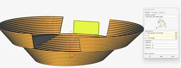
Fig 11. Completed “upper bowl” with jumbo-screen added.
Finally, what great stadium would be complete without some kind of covering? Using the tools we’ve walked through in this blog already, combined with complex surfaces and geometry options in FEKO, we can approximate a simple dome.
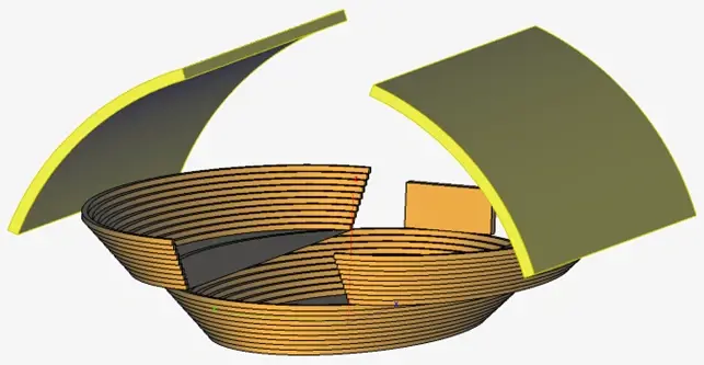
Fig 12. Parametrically defined stadium.
Now that our entire model has been defined, and it is completely defined via variables or transforms of variable-defined geometry, we can begin experimenting with manipulating the input parameters. Figure 12 above shows the following variable values:
- FieldLength – 110 m
- Playable length of field
- TierHeight – 2.5 m
- Playable width of field
- TierWidth – 2.5 m
- Width/Depth of each tier
- DomeThickness – 5 m
- Height of each tier
- DomeOpeningAngle - 40°
- How wide the stadium covering opens
We can make just a few modifications to these values to see quite a significant change, as displayed in Figure 13 below.
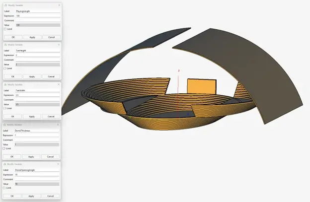
Fig 13. Parametrically modified stadium.
This concludes the brief overview of creating a parametrically modeled stadium. While this is a relatively simple example, it showcases the fundamentals of what is possible in Simcenter FEKO. Engineers can utilize features and conveniences discussed here to streamline design changes and to increase readability within CAD designs. What modifications would you make if you were designing and simulating your own stadium in FEKO? Be sure to check back in and subscribe to our YouTube channel as we continue with this World Cup discussion and simulation series!