
Running a Fluid Simulation (CFD) Study in Inspire 2022.3
Looking for CFD features? Look no further than Altair Inspire! Our latest blog highlights how to set up a CFD analysis in the latest release.
Altair recently released its latest version, Inspire 2022.3, and with that release was the exciting new fluid flow simulation that has been added to Altair Inspire! With the newest release, users can now run basic CFD simulations entirely within the Altair Inspire interface. In today’s blog I am going to go through a simple study using the new fluid simulation interface within Altair Inspire.
Step 1: Import or Create CAD Model
Since the newly added Inspire Fluids simulation is fully integrated into Inspire, users can take advantage of the existing geometry features in Inspire to create new geometry. Otherwise, users can import geometry, which is also a very common workflow. In my case, I am going to import my model, which is a piping intake system. Once the model has been imported, I can click on the Fluids menu to begin my fluid simulation, shown below in Figure 1.
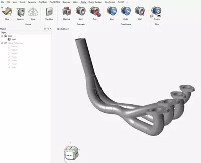
Figure 1: Model Geometry and Inspire Fluids Ribbon
Step 2: Set the Domain
The new Inspire Fluids ribbon is arranged like the other modules within Inspire, where users work their way from left to right to set up studies. This makes setting up fluid studies very easy to do. If we look at the Fluids ribbon, we notice on the very left are the domain icons, so we will begin with setting our domain. The domain options are solid and fluid, which represent solid geometry and fluid geometry, respectively, in a fluid simulation study. First click on the Solid icon and specify the outer pipe wall as Steel 304. Note, users can also create custom materials if they do not want to utilize the predefined library of materials.
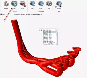
Figure 2: Setting the Solid Domain and Material Properties
After setting the Solid domain, I can now click on the next icon which is the Fluid Domain. Inspire gives users the option to specify an existing solid body as the fluid, or to create a fluid domain from a void. In our case we only have one solid body with a void, so we select the void option. The fluid domain void option is the smaller icon below the larger Fluid icon, shown in Figure 3. Immediately after doing this, Inspire will prompt the user to select the body with the void to add the fluid domain. For this scenario, we click on our solid pipe, and Inspire Fluids automatically finds the void and fills the domain with the fluid material we want to utilize. We will use gasoline as the fluid.
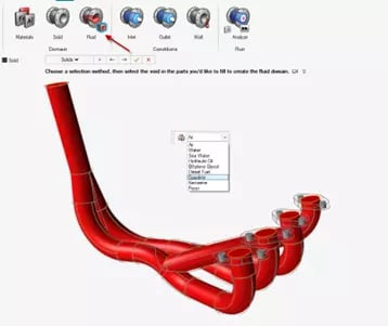 Figure 3: Setting the Fluid Domain and Material Properties
Step 3: Apply Boundary Conditions
Now that our Fluid and Solid domain have been set up, we can apply the boundary conditions in our scenario. Inspire Fluids gives users the ability to apply velocities, volumetric flow rates, and pressure as inlet conditions. For this example, since we have four inlets with varying velocities and temperatures, I can click on a face and specify the velocity and temperature at that location. I do this with each remaining inlets, which have different velocity and temperature conditions.
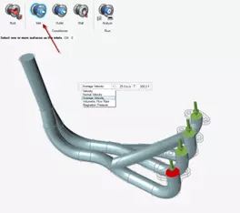 Figure 4: Setting the Inlet Conditions
Once our inlet conditions have been set, we just need to apply the outlet condition. In our case we can click on the exit face, and apply a pressure boundary condition which represents our outlet pressure condition, shown in Figure 5.
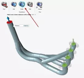 Figure 5: Setting the Outlet Conditions
Step 4: Run Settings
Now that our model has been set up, we can apply our run settings as a last step before we run the simulation. If we click on the analyze icon, it gives us the ability to adjust the resolution of our meshing options. Users can control the mesh resolution by the voxel size or the number of voxels. Additionally, the run options gives users the options to control the termination criteria for a simulation. In our case, I am going to utilize the default options for both the mesh resolution as well as the default options for the termination criteria (Figure 6).
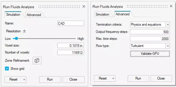 Figure 6: Inspire Fluids Run Options
Step 5: Postprocessing in Inspire Fluids
Now that our simulation has been run, users can take advantage of the integrated postprocessing within Inspire Fluids. Static plots, iso clipping, and dedicated streamlines can be created for fluid pressure, velocity, and temperature results. I want to look at the velocity variation in the system, via streamlines. I can easily create an animation by clicking on the play icon below the legend and animate the entire system.
 Figure 7: Inspire Fluids Results
With the use of Inspire Fluids I was able to set up and run a CFD study in a fraction of the time of traditional CFD tools. Results are also able to be postprocessed easily, through utilizing Inspire’s integrated postprocessor! For more information on Altair CFD please reach out to us here at TrueInsight, and we will be happy to answer any questions you may have.