
TrueInsight
Siemens/Altair Channel Partner
Menu


Permanent Analysis of Control Arm with Altair OptiStruct
Altair OptiStruct is known for being a high-end solver for implicit and optimization techniques. This post shows how to maximize its capabilities.
Permanent set analysis is one of the standard load cases in the auto industry which helps determine the max load the part/system can withstand and add reinforcements to designs if needed, it thus helps reduce the warranty costs.
When we have permanent set in the model, it means the material has been stressed beyond its yield point and is said to have undergone plastic deformation, which would need the part or system to be replaced as it might not function properly. For this study we are doing a non-linear static analysis on a lower control arm. We are using Altair products i.e., HyperWorks for preforming preprocessing, OptiStruct solver for non-linear analysis and HyperView for postprocessing.
FE Model Details
- Lower Control arm is modelled with tetrahedral elements with 3mm element size, and all the attachment points are connected using rigid elements (Fig 1)
- Units (Tons/mm3)
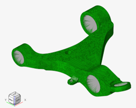 Fig 1: Model details
 - Steel material with Mat1 card image and values E 210000, Nu 0.33, Rho 7.85e-9 are used, also MatS1 option is checked on to capture the elastic plastic behavior, refer below (Fig 2) for Stress Vs Strain curve
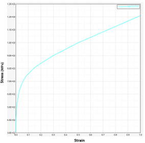 Fig 2: Stress Vs Strain curve
- The model is constrained at the 3 mounting locations with respective Dofs, refer Fig 3 below for details
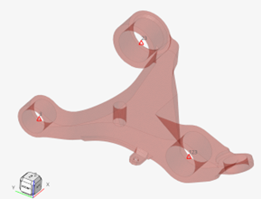 Fig 3: Constraints
 - The below Fig 4 shows all the Forces and moments applied on the model
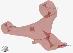 Fig 4: Loads
Analysis set-up
- The model is set-up with two load cases 1. Loading and 2. Unloading
- Both the subcases are run with Non-linear static analysis type with NLPARAM (LGDISP) i.e., large displacement activated
- We are outputting results for plastic strain, stresses and displacements
Results discussion
Loading subcase
- We can notice that the peak displacement is 1.02mm, and the max stress is 490 MPa which is exceeding the yield stress of 306 MPa, so the plastic strain of 0.0052 is also quite evident, refer Fig 5 below for details.
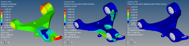 Fig 5: Results for Loading subcase
Unloading subcase
- The Unloading subcase is followed by the Loading subcase, with no load selected and CNTNLSUB option set to yes, which continues the subcase from previous subcase
- At the end of Unloading subcase, we can notice that there is a displacement of 0.048mm, which is permanent set, due to the part undergone plastic deformations, as we can notice that the plastic strains are at 0.0052, refer Fig 6 below for details.
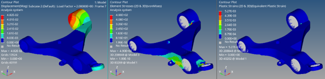 Fig 6: Results for Unloading subcase
Conclusion:
From the above study we can notice that once the part undergoes plastic deformation, there will be permanent set, in order to avoid permanent set, the parts need to be designed such that they do not exceed the yield stress limit. It is also very important to assess the max loads the parts/systems might be subjected to, as it will help ensure there is no permanent set in the material.
About Prashant Hiremath
Prashant Hiremath is working with Altair Engineering Inc. for the last 14 years; in his current role he is working as a Technical Manager–HyperWorks and responsible for supporting Altair Simulation Suite of Products. He received his M Sc. in Automotive Engineering from Coventry University, UK. He has 18 years of experience in Finite element analysis with focus on various domains i.e. Crash, Durability, NVH and Optimization. He also has experience with Product Design and Development.