TrueInsight
Siemens/Altair Channel Partner
Menu


Modifying Surfaces using X Form in Designcenter NX
Siemens Designcenter NX is known for creating organic shapes and surfaces easily, this blog will cover one of those channels for creation.
When it comes to advanced surface design in Siemens Designcenter NX, few tools are as powerful as X-Form. Whether you're sculpting organic geometry from scratch, refining an imported body, or reverse engineering a complex surface, X-Form gives engineers and designers a level of direct, intuitive control that parametric modelling alone simply can't match. This post walks through everything you need to know about the tool: What it does, how to use it, and why it belongs in your everyday NX workflow.
What Is X-Form?
X-Form is a freeform surface editing command within Designcenter NX that lets you modify the shape of surfaces and spline curves by dynamically manipulating nodes (poles), the control points that define the underlying mathematical structure of a NURBS (Non-Uniform Rational B-Spline) surface.
Rather than editing a surface indirectly through sketches, features, or constraints, X-Form gives you a hands-on way to push and pull geometry in real time. Think of it like working with a piece of virtual clay: you see the control cage overlaid on your surface, grab a point or a row of points, and drag the shape into the form you want. The result updates immediately, which makes X-Form especially valuable during conceptual design stages when you're still exploring the shape language of a part.
One important detail worth flagging early: X-Form works on both native NX geometry and imported geometry. That means if you've brought in a surface from a neutral file format like STEP or IGES, you can still use X-Form to refine or repair it, a capability that makes the tool indispensable for reverse engineering workflows.
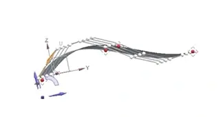
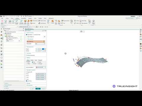
Fig 1: Siemens NX X-Form Design with control cage overlay
Getting Started: Selecting Your Surface
To launch X-Form, navigate to the Freeform section of the Surface tab (or search for "X-Form" in the command finder). Once the tool is active, select the face or surface body you want to edit. The moment you confirm your selection, NX overlays a cage on the surface, as seen in the image below.
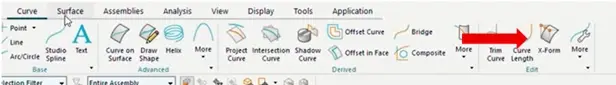
Fig 2: Siemens NX Ribbon with location of X-Form
At first glance, this cage can look complex, but it's the key to everything X-Form does. Each node acts as a handle. Move a node, and the surface moves accordingly, governed by the mathematical rules of NURBS interpolation.
Understanding Degrees and Patches
Before you start moving nodes around, it pays to spend a moment on the parameterization settings, specifically Degrees and Patches. These two parameters define how the control cage is structured and getting them right significantly affects both the quality of your result and how much control you have over the surface.
Degree controls how many nodes are available on your surface in each direction. A higher degree means more nodes, which gives you finer control over the shape, but also means the surface can become harder to manage. For most surface editing tasks, a degree of 3 (cubic) strikes the right balance between smoothness and controllability.
Patches work differently. Instead of adding nodes evenly across the surface, they split it into sections, giving you more control near the edges. This is especially helpful when you need tighter transitions or more precise blending with adjacent surfaces. However, using too many patches can create unwanted inflection points, subtle curvature reversals that may be hard to spot initially but become obvious in reflective lighting or curvature analysis.
Both Degrees and Patches can be set independently for the U and V directions, which are the two parametric directions of your surface (roughly analogous to rows and columns in a grid). This gives you asymmetric control: for example, you might want high resolution in the U direction to capture a complex profile, while keeping the V direction simple to maintain a clean sweep.
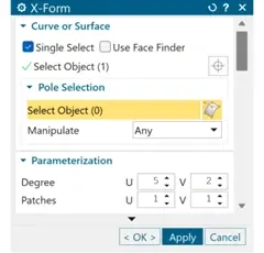
Fig 3: X-Form Dialogue menu
Manipulating Nodes and Polylines
Once your parameterization is set, the real work begins. You can select individual nodes, rows of nodes along a polyline, or the entire cage, and then move them using the standard NX dynamic handle. The movement can be constrained to a vector, a plane, or the normal surface, giving you precise directional control over how the shape changes.
A particularly useful workflow is to work progressively from global to local. Start by making broad, coarse adjustments with a simple cage (low degree, few patches), then increase the resolution incrementally to refine specific areas. This approach mirrors how sculptors work, rough form first, details later, and it keeps the surface cleaner than trying to achieve everything in a single highly-complex cage.
You can also select individual nodes and deselect their attached circles to enter what's effectively a "normal push" mode, where dragging moves the surface point perpendicular to the local surface tangent rather than along a global axis. This is ideal for adding subtle bumps, recesses, or organic curvature where a fixed-direction move would feel unnatural.
Planarizing
One of the more nuanced features in X-Form is the ability to planarize nodes, to force selected nodes into a flat plane. This matters when you want a section of your surface to be perfectly flat, or when you need a row of nodes aligned before blending into a mating surface.
NX offers several planarization options: At Plane (align to a defined datum plane), At the Node (align relative to a specific node), and Best Fit Plane (NX calculates the optimal plane based on the selected nodes' existing positions). Each suits different scenarios, and it's worth experimenting with all three to build intuition.
A newer addition, introduced in the June 2024 release, is the View-Based Planarization option. This projects a selected row of nodes onto a plane oriented perpendicularly to your current view, passing through the two nodes that are furthest apart. In practice, it's a very fast way to flatten out a row of nodes that looks misaligned from your working view, without having to define a datum plane manually.
Maintaining Symmetry
Freeform editing tools often come with a hidden risk: breaking the symmetry of a part that's supposed to be symmetric. NX addresses this directly in X-Form by allowing you to define a symmetry plane. Once set, any edits you make to the surface are mirrored automatically across that plane, ensuring that both sides of your model remain identical throughout the editing session.
This is especially valuable in automotive and consumer product design, where parts like door panels, hood scoops, or product casings must be perfectly symmetric. It removes the tedious and error-prone step of manually mirroring edits after the fact.
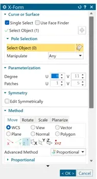
Fig 4: X-Form Menu with Method and Symmetry Options
Practical Applications
The use cases for X-Form span a wide range of engineering contexts. In Class-A surfacing (the high-quality exterior surfaces used in automotive and consumer product design), X-Form is a go-to tool for shaping panels and adjusting highlight lines. In industrial design, it enables rapid exploration of organic forms without being constrained by parametric feature logic. In reverse engineering, X-Form lets engineers rebuild production-quality surfaces from scan data efficiently and accurately.
Even in more conventional mechanical engineering workflows, X-Form finds a role wherever a surface needs refinement that traditional feature-based modelling can't easily produce complex inlet geometries, ergonomic grip surfaces, or aesthetic cover panels are all good candidates.

Fig 5: Real-world examples of X-Forms best applications
Getting the Most Out of X-Form
A few practical tips that make X-Form significantly more productive:
- Start with the minimum number of nodes needed to achieve your rough shape, then increase resolution only where necessary. Clean, low-degree surfaces are easier to blend and less likely to develop curvature problems downstream.
- Always run curvature or reflection analysis after editing to catch inflection issues early, they're far easier to fix while you're still in X-Form than after the session is closed.
- When working on surfaces that need to blend into adjacent geometry, use the Deviation Gauge not just against scan data, but against the neighboring surfaces to check tangency and curvature continuity.
X-Form in Designcenter NX is one of those tools that repay investment. It bridges the gap between rigid parametric modelling and true freeform sculpting, giving engineers the control they need to create surfaces that are not just geometrically valid, but genuinely well-crafted. To learn more about X-Form or anything else in Siemens NX, don’t hesitate to reach out to us!