
TrueInsight
Siemens/Altair Channel Partner
Menu



What’s New in Inspire 2026.1: Optimizing with a Porosity Constraint from Inspire Cast
New to Simcenter Inspire 2026.1 users can now factor casting porosity within a topology optimization study.
Topology optimization in Simcenter Inspire finds the most efficient load path for a given set of constraints. In previous versions, those constraints could account for loads, restraints, and even manufacturing method, but there was no way to control for one of the most common casting defects: porosity. In casting, porosity is the voids left behind by shrinkage and trapped gas during solidification, and in previous versions, Inspire had no way to factor those locations into the optimization. A part could get optimized as if it were fully dense everywhere, even though the casting process was always going to leave real voids in it.
With Inspire 2026.1, you can now pull results directly from an Inspire Cast run and factor porosity into the topology optimization as a manufacturing constraint, so the solver builds in the extra support those weak spots need, to hit your target safety factor. In this blog, I am going to walk through how to do that so you can start optimizing your own cast parts with this workflow.
Step 1: Run a Casting Study in Inspire Cast
Our first step is to run a casting analysis, since its results are what feed into the topology optimization later on. In our case, I am running a gravity sand casting study on an aluminum bracket. Once the scenario finishes, I can see porosity issues at the center of the part (Figure 1) this is exactly the kind of result we want the topology optimization to be aware of.
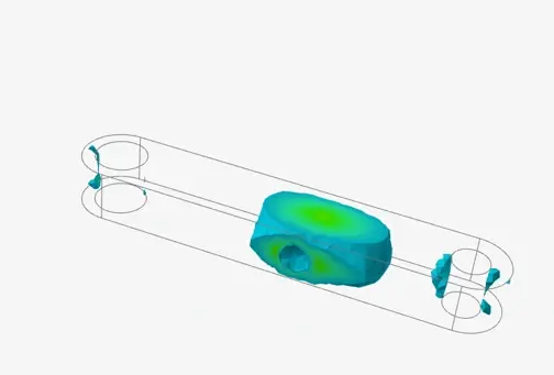
Figure 1: Porosity Results in Inspire Cast
Step 2: Take Results from Inspire Cast and Put into Inspire Directory
With our Inspire Cast analysis complete, we can carry those porosity results into the topology optimization. Every Inspire Cast simulation writes its results to a solver directory, and one of those files is a JSON file containing the critical material and porosity information from the run. That JSON file is what needs to be placed in the Inspire directory where you will run your topology optimization. In our case, I will grab the JSON file and drop it into the folder where I will be running the topology optimization in Inspire (Figure 2).
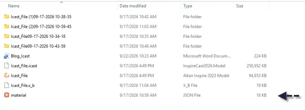
Figure 2: Inspire Cast JSON file Placed in Inspire Directory
Step 3: Run Inspire Topology Optimization with Porosity Constraint
Now that our JSON file is in the Inspire directory, we can set up the topology optimization as usual. The bracket is restrained on one side, and a structural load is applied on the other. The only difference from a standard run is a new Porosity Constraint section in the Run Optimization dialog, where the only input is a minimum safety factor in this case, 1.5 (Figure 3). Behind the scenes, Inspire uses that JSON file to know where the part is predicted to have porosity, then targets that safety factor in those specific regions rather than treating the whole part as fully dense material. One important note: if you skip placing the JSON file from Inspire Cast into your Inspire project directory, the Porosity Constraint option has nothing to work from, and it will not be applied.
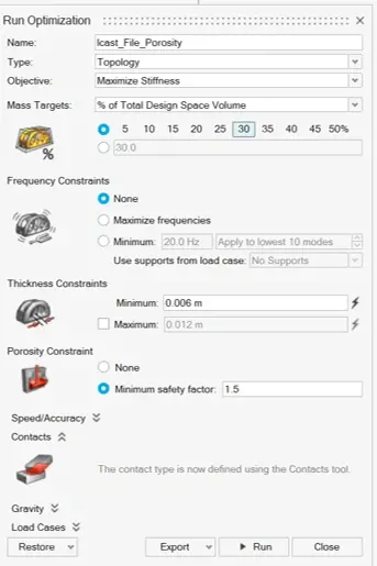
Figure 3: Porosity Constraint for Topology Optimization in Inspire
With the constraint set up, we can run the study. I ran it twice once without the porosity constraint and once with it keeping every other load and constraint identical between the two, so porosity is the only variable that changed. With the porosity constraint applied, Inspire adds a bit more supporting mass around where the potential void would be during casting. That extra mass holds our target stiffness and safety factor even with a known casting defect in that region. Essentially, we are optimizing for the part we will actually get off the foundry floor, not an idealized, fully dense version of it. Figure 4 shows both results side by side: the part optimized without the porosity constraint on the left, and the part optimized with it on the right.
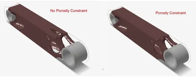
Figure 4: Optimized Parts, Left No Porosity Constraint and Right Optimized Part with Porosity Constraint
Looking at Figure 4, you can see more supporting mass applied in the porosity-constraint scenario, directly in response to the potential void in the interior. That extra material ensures the part still meets its stiffness and safety requirements even with a known porosity issue built into the casting process. I hope this tip helps you optimize your own cast parts with more accuracy in your next topology optimization run. To learn more about Simcenter Inspire, Simcenter Inspire Cast, or any other Siemens product, please contact us here at TrueInsight!