
TrueInsight
Siemens/Altair Channel Partner
Menu


How to Simulate Solar Radiation for a Sunroom in HyperMesh CFD
HyperMesh CFD is a streamlined UI which provides CFD workflows for aerodynamics, aeroacoustics, internal flow, multiphase flow, thermal and moving mesh.
We are in the dead of winter here in the Northeast, and I can feel the cold every single time I am outside for my morning walks. Sometimes, I wish the dog could walk herself, on these brutal February mornings. However, much to my chagrin that isn’t culturally acceptable, so I continue on my normal cold walks. I noticed recently on one of these cold morning walks, that many of the houses in my neighborhood have sun porches; porches enclosed by glass windows. This got me thinking, I wonder if we could simulate how efficient a glass sunroom could be, could these sunrooms be utilized efficiently during winter? Thus, for today’s blog, I am going to simulate a glass sunroom in HyperMesh CFD and see how the thermal effect of solar radiation heats a room.
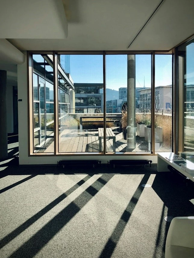 Figure 1: Sunroom getting Peak Sunlight During Winter
For those unaware, HyperMesh CFD is a computational fluid dynamics tool, that can solve fluid flow problems, heat transfer, aeroacoustics, as well as numerous other complex Multiphysics problems. The tool utilizes the preprocessing power of HyperMesh meshing and integrates it for CFD. It should be noted you can also setup CFD problems in Altair SimLab, but in today’s blog I am going to focus on setting up this problem in solely HyperMesh CFD.
Step 1: Create/Import Geometry of Glass Porch
HyperMesh CFD gives users access to several tools in addition to the CFD solver set included with HyperWorks. In my case, I created a sample sunroom based off stock dimensions for a sunroom I grabbed online and generated the CAD model in Altair Inspire. However, keep in mind, if your workflow is importing native CAD files directly into HyperMesh CFD, you can easily do that as it accepts all major CAD formats for import. Once the geometry was created, I imported it into HyperMesh CFD as shown below in Figure 2.
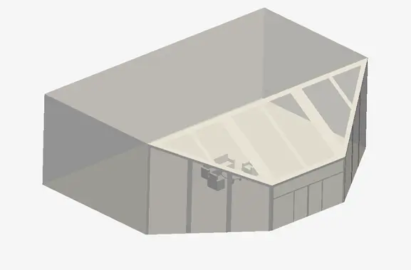 Figure 2: Sunroom CAD from Altair Inspire imported into HyperMesh CFD
Step 2: CFD Project Setup
HyperMesh CFD’s graphical user interface (GUI) is set up to take you from project creation through meshing and solving in an easy workflow. We can begin our process by setting our overall project conditions. In this case we want to model a transient problem, because solar radiation changes with respect to time in the day. Additionally, since we are modeling air we can select incompressible single-phase flow, and we will activate heat transfer (Figure 3).
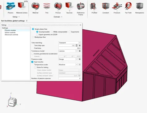 Figure 3: Project Settings for thermal Problem
Now that our project settings have been specified, it is a matter of keying in the boundary conditions for our problem. Our first boundary condition is on the roof, where I modeled two small vents on top to simulate a small ventilation system. The vents were modeled to be small to represent a typical vent for a sunroom (Figure 4).
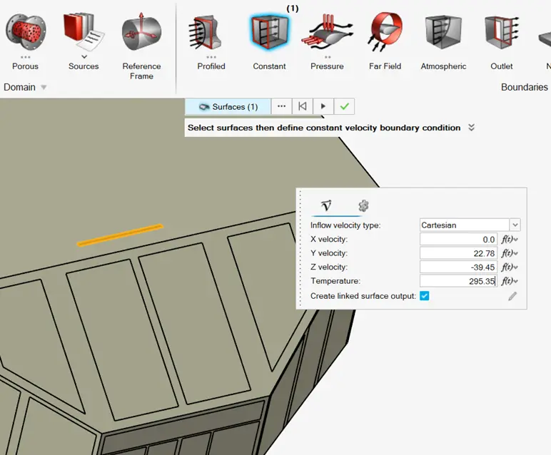 Figure 4: Inlet Boundary Condition on Roof
With HyperMesh CFD, I can easily click on the constant boundary condition icon then select the face and key in the values. In Figure 4, we can see the small face that was selected had air flowing in the X,Y,Z directions and the temperature applied was 295 Kelvin (71°F), this would reflect a typical air flow for a small air vent. I then applied an ambient pressure boundary condition on the other vent shown in Figure 5.
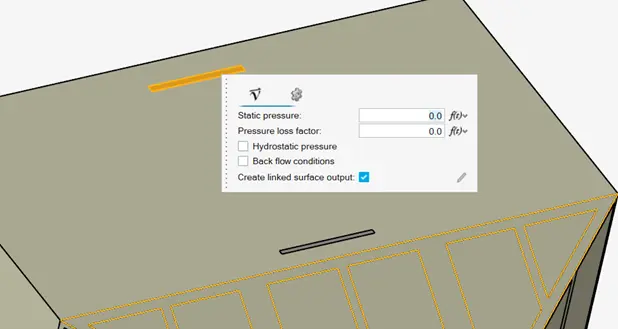 Figure 5: Ambient Pressure Boundary Condition on Other Vent
Once the flow boundary conditions were set, we can key in the solar radiation values. Within HyperMesh CFD, we have a nicely automated method of keying in multiple emissivity values quickly. In our case most of the model will be a black body. If you are unfamiliar with what a black body is, it just means radiation is absorbed into the object, so in our case the walls are absorbing the solar radiation. For black bodies, it has no reflectivity or transmissivity so that is what we key in for most of the model. Note, most of the locations of where the black bodies will be, they are represent solid walls. Whereas, the glass windows in our interior are not a black body, so we key in reflectivity and transmissivity values for the glass. All values of emissivity are shown in Figure 6.
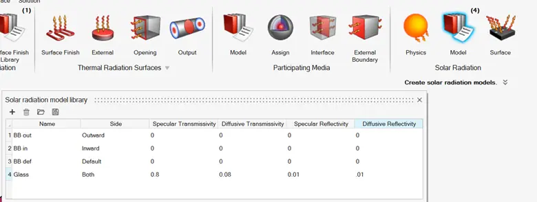 Figure 6: Emissivity Values for Windows and Walls
Now that the emissivity values are keyed in the process of applying them, just requires us to click on the surface option under the Solar Radiation menu and to then assign a surfaces its respective emissivity. As I mentioned before, most of the model will be a black body as they reflect a sunrooms walls without window, whereas the windows will not be modeled as a black body. In figure 7, I am applying it to the glass windows, but this approach was utilizes for all of the other walls with just the black body values applied.
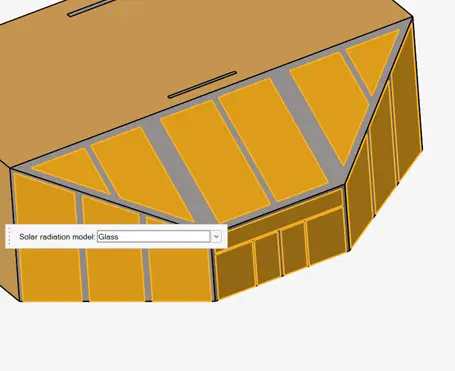 Figure 7: Assigning Glass Emissivity to Windows
At this point we just need to apply the solar radiation flux. Like I discussed previously, the solar radiation changes with respect to time, to reflect the suns place in the sky during a typical day. In our case I am just looking at a period over 30 minutes, however, you could key in whatever time you are interested in! To input the solar radiation option, I click on the solar radiation value and I key in the solar flux values with respect to time and the X,Y,Z coordinates (Figure 8). The option to key in changing radiation values, reflects what would be happening in real life in our sunroom! Now that our boundary conditions have been applied, we can apply our mesh and solve.
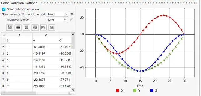 Figure 8: Applying Flux for the Solar Radiation in the X,Y, and Z Directions
Step 3: Generate CFD Mesh and Solve
The meshing workflow in HyperMesh CFD is set up to be easy, but it utilizes the power of HyperMesh to so it can also handle complex geometries. In our case, I will first go to the surface meshing option and specify a setting that will ensure that there are at least 5 elements across thickness (Figure 9). Surface meshing in HyperMesh allows user to locally refine for advanced geometry. In my case, since most of my shapes are cartesian, I can use a global size setting without a need for advanced refinement.
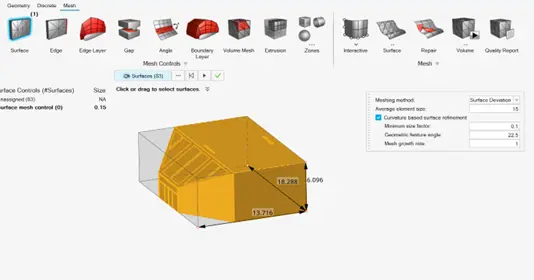 Figure 9: Surface Mesh Settings on Sunroom
After we generate our CFD mesh we can apply our volume mesh and boundary layer settings. Similar to what I assigned for the surface mesh, I apply a volume mesh setting that ensures I have enough volume elements through thickness. It should be noted, if I was worried about local turbulence, I could have refined the mesh further. However, in my case, I expect the flow to be laminar, so the mesh settings I have applied are adequate (Figure 10).
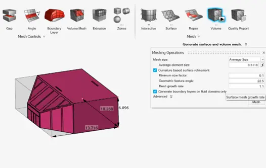 Figure 10: Volume Mesh Settings on Sunroom
Now that our model is meshed, we can run our model. HyperMesh CFD enables users to specify how many processors they wish to utilize. The beauty of HyperMesh CFD is it can handle small to very large models by leveraging multiple processors. In my case the mesh density is not overly fine, so will just utilize 4 cores. I am also going to set an initial temperature of ambient as well, with no circulating flow initially (Figure 11).
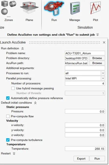 Figure 11: Processor Settings for HyperMesh CFD
Step 4: Postprocess Results
Our model ran in less than ten minutes on a four-core machine, and I can now visualize the results at each time step. In my case I want to generate a transient plot showing the temperature results with respect to our total time. In HyperMesh CFD I can hide exterior surfaces so I can see interior surfaces easier. In my case, I hide most of the exterior walls, I do keep the window frame walls up for context and then I create my animation. Through animating the results, I can see that the temperature stays within an acceptable range of around 71 degrees Fahrenheit (Figure 12). I can also see how the temperature disperses through the room as the sun moves position and the solar radiation adjusts.
 Figure 12: Temperature of Sunroom over 30 minutes
As you can see the process to simulate thermal scenarios in HyperMesh CFD is easy and efficient. Anybody can leverage the power of Altair! I was able to create a CAD model, preprocess and postprocess this entire scenario all on the Altair Platform, without having to build a physical prototype. I now know that if your windows are thermally efficient, you can sit in these rooms during our cold winters here in the northeast. If you still have those old single pane windows, you might want to do otherwise! For more information on Altair HyperMesh CFD or other Altair products please reach out to us here at TrueInsight, and we will be happy to answer any questions you may have.