TrueInsight
Siemens/Altair Channel Partner
Menu


How to use Altair CFD to design Formula 1 Nose Cones
Learn how to use Altair CFD tools to design Formula 1 nose cones. Explore the importance of simulation in aerodynamics and the power of Altair CFD.
In mid-November, Formula 1 is heading back to Las Vegas after a 40-year hiatus. The race will include a portion of the track on the Las Vegas strip, and the race will be a night race which will be a visual spectacle with all the lights of Las Vegas. As a result, there is a ton of excitement for this upcoming race, I am deeply excited to see how this race pans out and to see the Formula 1 drivers race around Las Vegas at night. In todays’ blog I am going to go through how using Altair CFD tools could potentially help in design for a Formula 1 team’s nose cone.
Formula 1 Background
First, if you are unfamiliar with Formula 1, it is generally regarded as the highest class of automobile racing in the world. Race cars (Figure 1) in Formula 1 push the limits of speed and are typically the fastest road racing vehicles in the world. It is not uncommon for average speeds of vehicles in Formula 1 to be around 130 Mph with max speeds reaching nearly 230 Mph. As a result of these vehicles being pushed to their limits, there is significant engineering design on every vehicle in the Formula 1 circuit. Many of the Formula 1 racing teams will have hundreds of engineers working on everything from aerodynamics to engine design, to control system design.
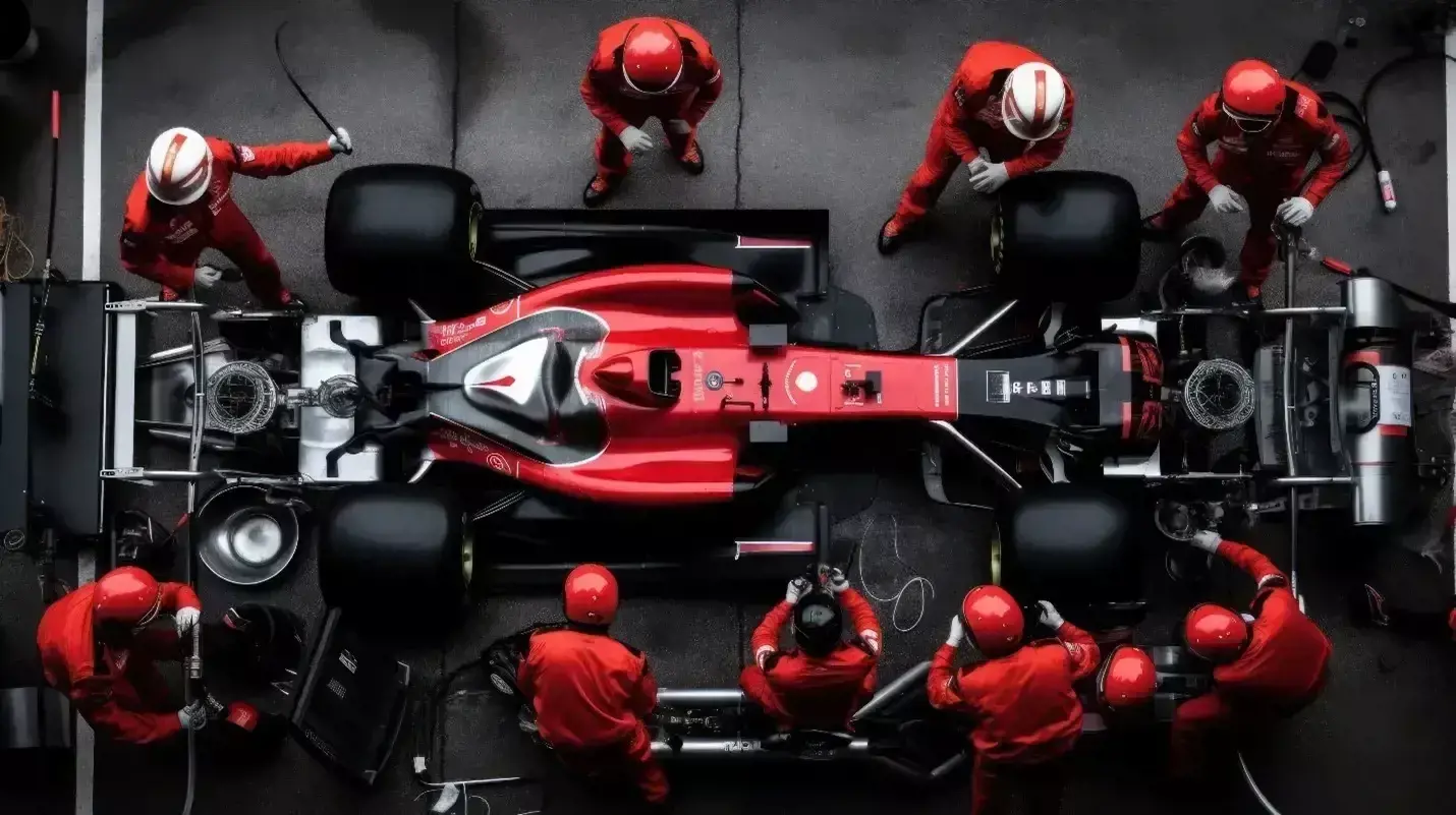 Figure 1: Formula 1 Car and Team on Race Day
A typical Formula 1 car can cost anywhere in the range of 12-16 million dollars, and since teams have two drivers/vehicles, that puts the cost of vehicles per each team around 30 million dollars! Therefore, it is imperative that the vehicles that go out on race day have been rigorously tested and simulated.
Nose Cone Design
The nose cone (Figure 2) primary purpose is to redirect air flow to the side of the Formula 1 car rather than directly into the cockpit. Additionally, by feeding air to the side of the vehicle it aids in cooling the vehicle and increases efficiency. The more efficient a nose cone, the better the performance for a Formula 1 car.
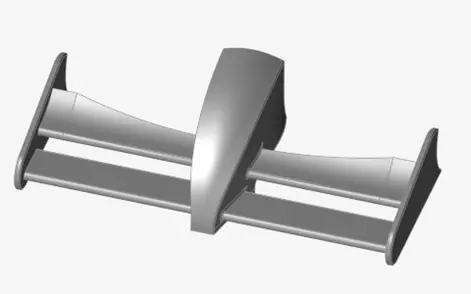 Figure 2: CAD Representation of a Formula 1 Nose Cone
When nose cones are being designed great investment is put into simulation, specifically Computational Fluid Dynamics (CFD) and Finite Element Analysis (FEA). Engineers will rigorously test various scenarios of how air flow will move over the nose cone as well as simulating the structural effects of the wind force. In this blog I am going to lay out how to simulate the air flow over the nose cone, and in a future blog I am going to look at how to simulate the structural effects of the wind loads.
Step 1: Nose Cone Geometry Creation and Import
Unfortunately, I do not work for a Formula 1 team and so I am not privy to specific nose cone dimensions or CAD! With that being said, the power of Google gave me the ability to look at a variety of different nose cones, and to then save those images. I then took those images and imported them into Altair Inspire Studio to create my own nose cone model. Altair Inspire Studio gives users the ability to sketch designs based off images by inserting images into Inspire Studio to use as a baseline. I utilized an image for a nose cone from the Ferrari team (Figure 3) and then adjusted the model accordingly (I changed a few items from the image i.e. radii and fillets, and simplifying some complex surfaces).
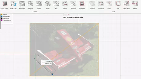 Figure 3: Altair Inspire Studio Nose Cone Geometry Creation
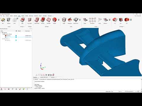
Upon finishing my CAD model in Inspire, I was able to export the parasolid model so I could import it into Altair SimLab for CFD analysis. Note if you already have a CAD tool you can import native files directly into SimLab. SimLab imports all the major CAD formats as well as all the neutral CAD formats. In my case, my Inspire Studio file is saved out as a Parasolid, and I imported that file into SimLab to begin my CFD setup (Figure 4).
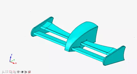 Figure 4: SimLab Nose Cone Geometry
Step 2: Create Mesh for CFD Study
Altair SimLab is a Multiphysics tool, so it has capabilities for both FEM and CFD. In our case we are going to run a CFD study, and we are going to utilize the Acusolve solver for this study. Note if we were doing full vehicle aerodynamics, Altair has an LBM solver; ultraFluidX, in that case I would have used that CFD solver. However, since we are just looking at the nose cone I am going to use the Acusolve solver. Acusolve is an FEM based Navier Stokes code so it has capabilities to easily couple CFD studies with structural analysis. Like I indicated previously, in a future blog I am going to utilize these CFD results in FEA, so that is why I want to utilize Acusolve in this case.
Meshing in SimLab is very user intuitive, in my case I am going to mesh both the nose cone as well as the air fluid domain surrounding the nose cone. I can take advantage of specific boundary layer settings, as well as mesh controls to ensure that the mesh will be accurate for my simulation (Figure 5). In my case I apply appropriate mesh sizes to make sure that I have at least 5-10 elements across thickness for various locations on my nose cone. This mesh size will ensure I have reasonable simulation results.
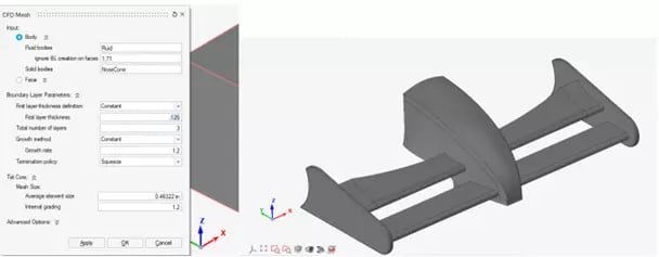 Figure 5: SimLab CFD Mesh Settings and Mesh of Nose-Cone
Step 3: Apply Boundary Conditions
With meshing done we can now apply the boundary conditions in our scenario. The first thing we need to set is the type of problem we are going to be solving in Acusolve. In SimLab we click on the Flow Solution shown in Figure 6. After clicking on the Flow icon (Figure 6), a box pops up with the settings for the study. In our case we are going to run a steady state problem with no heat transfer and the default turbulence settings.
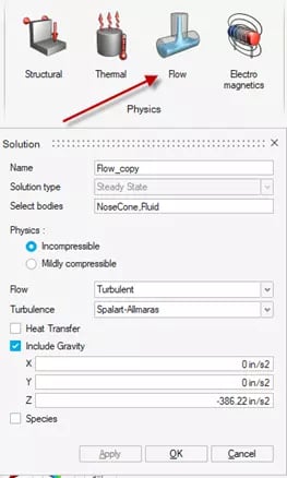 Figure 6: CFD Study Settings.
Now that we have started the study, our next step is to apply our boundary conditions in our problem. SimLab CFD gives users a variety of inlet and outlet conditions we can apply. In our case we are going to apply a far field since we are dealing with external flow over our nose cone. We can specify the inlet and outlet faces of the air fluid domain and we specify a velocity of 2030 in/s (about 115 mph). The Far Field settings also give us the option to specify custom turbulence or eddy viscosity settings (Figure 7). I am going to utilize the default turbulence and eddy viscosity settings. After applying this boundary condition, I am now ready to run the simulation.
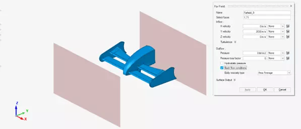 Figure 7: Boundary Conditions for Nose Cone
Step 4: Postprocess Results of Simulation
Now that we have run the scenario, we can postprocess and visualize what is happening to the nose cone at average speeds during the race. One of the first things I want to check is to see what the velocity profile is over the nose cone. SimLab’s easy to utilize post processing gives users the ability to create cut planes in any direction you want. In my case I am going to look at the velocity profile through the top and lateral views of the nose cone.
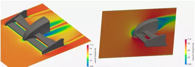 Figure 8: Top and Lateral Views of Velocity Profile in the nose cone
Through looking at the velocity profiles (Figure 8), you can see that the airflow directly in the cockpit has a minimized velocity. Additionally, the air flow directs down the side of the vehicle. From a design perspective this is what we would want for a nose cone for a velocity profile. The other thing I want to look at is the pressure gradient on the nose cone, so I am going to create a pressure plot of just the nose cone.
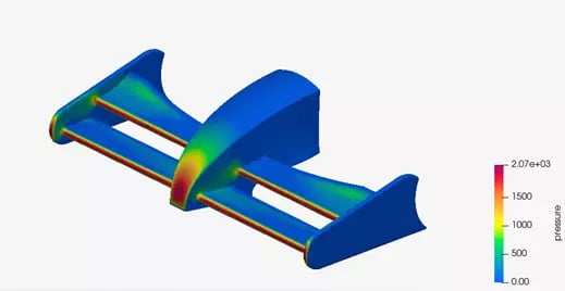
Figure 9: Pressure Profile of nose cone
One of the clear things from the pressure plot (Figure 9) is that the largest pressure reflects where the air is hitting the nose cone. It is nice to see that downstream, the nose cone pressure decreases which indicates air flow is being diverted away from critical areas. This is something I would want as a designer! The beauty of Sim-Lab is I did not have to build a physical prototype to test these scenarios. Altair’s CAE tools enabled me to create, simulate, and postprocess my nose cone design in a fraction of the time!
I hope this blog has illustrated the power of Altair CFD, and how easy it is to run and set up a fluid flow problem. Whether you are working for a Formula 1 team, doing machine design, or doing product development, Altair’s CFD tools can help reduce your product lifecycle. If you have any more questions about Altair CFD or any Altair solution, please reach out to us!