TrueInsight
Siemens/Altair Channel Partner
Menu


How to Import Geometry and Mesh with Altair Feko
In this post we look at how users can import geometry and mesh into Altair Feko.
Altair Feko is a powerful 3D electromagnetic design, analysis, and simulation software for high frequency devices. While Feko has a full suite of CAD tools, allowing engineers and designers to start from scratch directly in the tool, many users may find themselves already starting with existing geometry or mesh files from third-party software. Today, we will take a look at how to import files like these into the Feko environment.
Importing Geometry
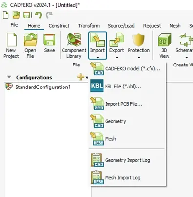
Fig 1. The Import options on the Home tab in Feko.
To begin, we will simply locate the “Import” button on the “Home” ribbon, as seen in Figure 1 above. You will notice that several types of files can be imported, such as native Feko files, PCB files, geometries, and meshes. For now, we will choose the “Geometry” option, which opens the dialog box shown in Figure 2 below. There, we can see that several file types are supported, including CATIA, Parasolid, STEP, and others, meaning that Feko can almost certainly handle your existing geometry file.
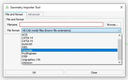
Fig 2. Geometry file types available for importing in Feko.
Depending on your imported file type, some additional steps may be necessary before importing, which can be accessed on the “Advanced” tab, as shown in Figure 3 below. This will allow you to apply units to the model (if the file does not already have them), apply healing, or scale the size of the geometry by a prescribed factor.
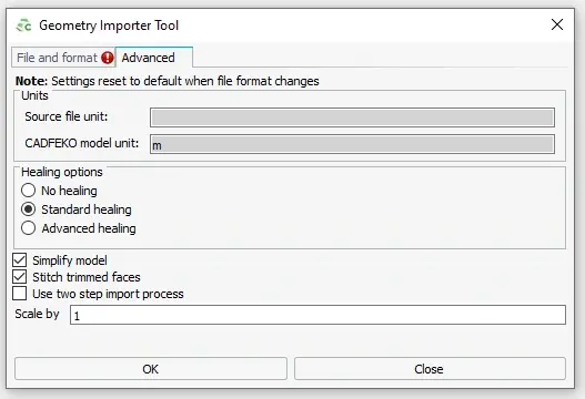
Fig 3. Advanced options for importing geometry in Feko.
After clicking “OK,” we have successfully imported our Geometry! Figure 4 below shows the example horn antenna that we have brought into Altair Feko.
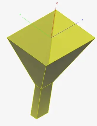
Fig 4. Imported horn antenna geometry in Feko.
Geometry Transformation Options
Now that our model has been imported into Feko, we have the full suite of the software’s CAD tools at our disposal. We can add additional geometry, edit the existing geometry, or apply any necessary transform options. Figure 5 below offers a high-level highlight of what is available in this regard.
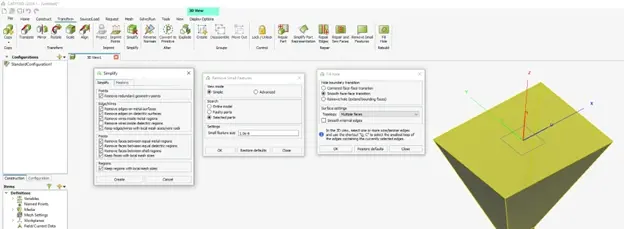
Fig 5. Geometry transformation tools available in Feko.
As an example of geometry healing after importing it into Feko, I added some artificial bolt holes at the base of the antenna, shown in Figure 6 below. Small holes like this, or other small features, often exist in the highly detailed CAD files for a device, but we may not necessary want to include them in the simulation for a variety of reasons, such as improving mesh quality or reducing simulation time. In this case the hole locations at the bottom will not influence our high frequency results, so its ok to eliminate them.
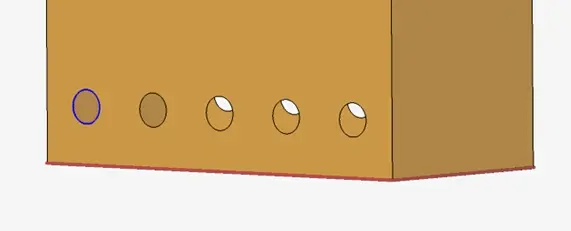
Fig 6. Base of Antenna with artificially added bolt holes.
We will use the “Repair and Sew Faces” tool in the “Transform” ribbon of Feko, as seen in Figure 7, to automatically locate and fill these holes. While this is a relatively simple example, the same logic could be applied to far more complex designs, drastically improving simulation runtimes.
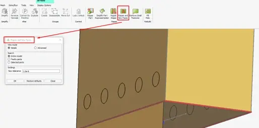
Fig 7. Base of Antenna with artificially added bolt holes filled in.
Importing Mesh
Geometry is not the only preexisting file that Altair Feko can import; in fact, this software can also import a wide variety of mesh files. Some of the mesh file types available for importing are shown in Figure 8 below. In addition to the file types shown in that figure, the following file types are also supported: NEC, I-DEAS UNV, FEK, Voxel mesh, CADFEKO mesh, and Feko HyperMesh.
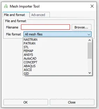
Fig 8. Mesh file types available for importing in Feko.
Just like our geometry import tool, our mesh import tool also has an array of advanced options to assist with bring your files into the Feko environment. Depending on your file type, you can adjust which mesh elements are brought in, convert the mesh, and scale unitless mesh files to meters, as shown in Figure 9.
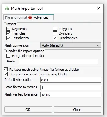
Fig 9. Advanced options for importing mesh in Feko.
After importing the mesh of our horn antenna with a “Scale factor to metres” of 1, we have the mesh of our model successfully imported into Feko, depicted below in Figure 10.
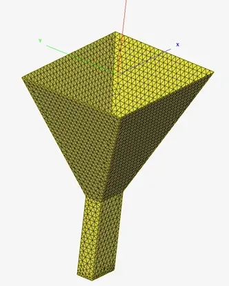
Fig 10. Imported horn antenna mesh in Feko.
Validating Mesh
One last step is to validate that our mesh was imported correctly. In this example, we used an STL file to import the horn antenna into Feko, meaning the mesh was unitless before it was imported. Since we set our scale factor to 1, one “unit” in the mesh file will convert to one meter in Feko. We can check this by using the measure tool, as shown in Figure 11 below, to measure the height of our device from one end to the other. I have reduced the opacity of the mesh so that we can more easily see the blue line covering this distance in the image. As we can see, the device is 76.1965 cm tall, which matches our expectations; we know this because the mesh was scaled by a factor of 1 to meters, and it is 0.761965 meters tall.
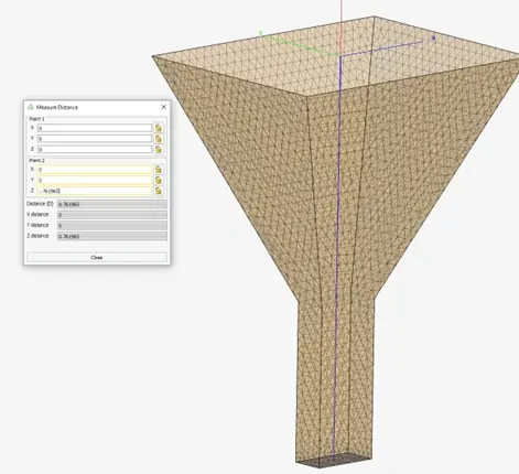
Fig 11. Verifying Mesh size using Measure tool.
Once we are satisfied that our mesh matches our design expectations, we are ready to move forward with the electromagnetic setup of our simulation. If you would like to learn more about importing files into Altair Feko, or if you would just like to learn more about Altair Feko or the Altair suite of software solutions in general, please be sure to check out these blog posts regularly and subscribe to our YouTube Channel. As always, if you have any questions, please feel free to reach out to us directly!