
TrueInsight
Siemens/Altair Channel Partner
Menu


How to run a Heat Transfer Study in Inspire Fluids 2023
Altair Inspire continues to get better with each release. In 2023, added CFD capabilities have been added. Check this post out to see how its done.
Altair recently released Inspire 2023, and within that release one of the major highlights was the brand-new implicit modeling tools. However, within that release came some other great features, specifically conjugate heat transfer was added to the Inspire Fluids Solver. Conjugate heat transfer allows users to simulate heat transfer between fluids and solids. In today’s blog I am going to walk through a basic conjugate heat transfer scenario for a heat exchanger.
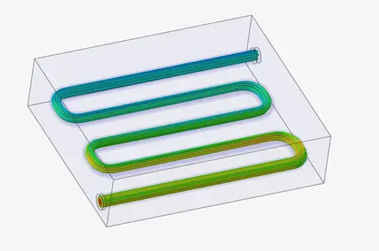
Figure 1: Heat Exchanger Model
Step 1: Create Heat Exchanger
With Altair Inspire, users can import geometry from various native and neutral CAD formats. However, Altair Inspire also has the ability to create CAD models with its geometry and sketching ribbons. In my case, I am going to take advantage of these modeling tools and create my own unique geometry in Inspire. However, note you can utilize the heat transfer features for imported bodies, so feel free to utilize that workflow on your models if you plan to import and run heat transfer in Inspire.
Since I am not importing a model, I need to create a model in Inspire. In my case, I want to create a basic heat exchanger. I first begin by creating a basic sketch and sketching out a piping arrangement which will have water flowing through it. I do this by going to the sketch menu in Inspire and then utilizing the polyline feature, and adding fillets and dimensions, see below in Figure 2 for dimensions.
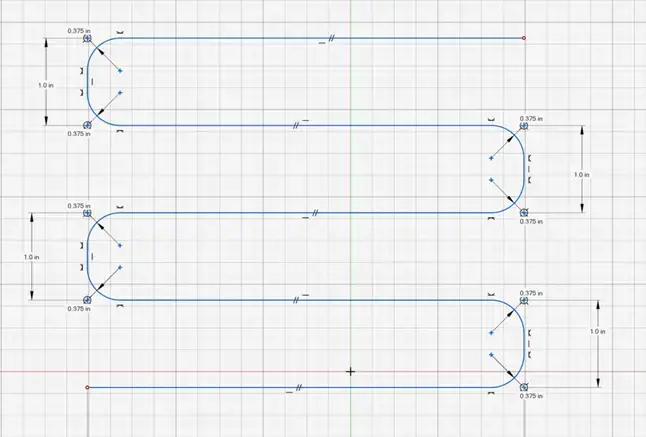
Figure 2: Tube Dimensions
After finishing my dimensions, I now create my 3D shape of the tube. Within Inspire it has a nice, automated feature to create pipes very quickly, I click on this feature and then click on my sketch, and key in a thickness and diameter representative of what I want my internal pipe to be (Figure 3). After creating the internal pipe, I create a simple enclosure that surrounds the pipe by creating a box and using a boolean subtraction to create the final body (Figure 3). Now with my model created, I am ready to begin to setup my heat transfer study!
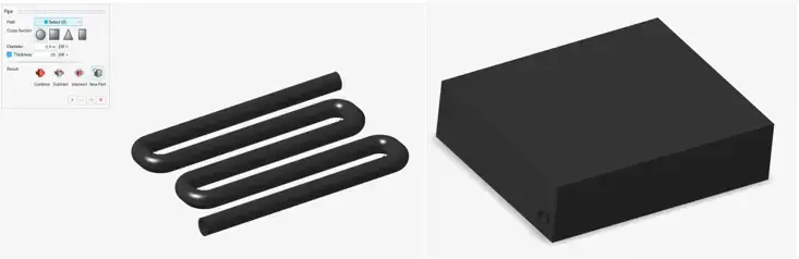
Figure 3: On Left: Internal Pipe Geometry and On Right: Enclosure with Internal Tube
Step 2: Specifying the Inspire Fluids Domain
Now that we have a 3D CAD model built, we are ready to run our conjugate heat transfer study. The Inspire Fluids simulation features can be found under the Fluids Ribbon (Figure 4).

Figure 4 : Altair Inspire Fluids Ribbon
Our first step is to specify our materials for the solids in our analysis, which we do by clicking on the Static Solid icon. The enclosure and the internal tubing will be an Aluminum material (Figure 5). Note users, have the ability to key in their own material if you have specialized materials not in the Inspire material database.
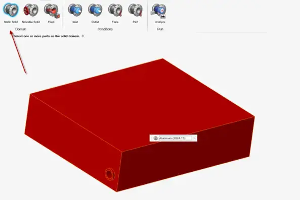
Figure 5: Specifying Solid Material for Enclosure and Tube
Our next step is to specify the fluid for our model. The great thing about Inspire Fluids is it has an "automatic cavity detector" so if you have not created a solid body from the fluid, Inspire can recognize it automatically. For our model our interior tube is hollow so we want to utilize this feature. However, if we had defined the fluid as a solid body during CAD modeling, we would not have to utilize this feature, and could specify the solid body as the fluid. Once we click on the cavity detection tool and click on an interior face of the tube it automatically builds the fluid body and it gives us the option to specify the fluid. In our case we are going to model water as the internal fluid flowing through the pipe, and this is shown in Figure 6.
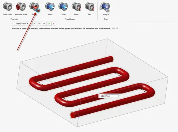
Figure 6: Creating Water Fluid Domain
Step 3: Apply Boundary Conditions
At this point, we are now ready to apply boundary conditions in our model. Since this is a heat transfer application, the fluid moving through the pipe will be at a colder temperature, while the rest of the enclosure is heated up. We will need to key in our inlet and outlet conditions of our water. I apply an inlet condition, by clicking on the circular face of the interior fluid and I key in a volumetric flow rate of .05 m3/s and a temperature of 272 K (30 F°), shown in Figure 7.
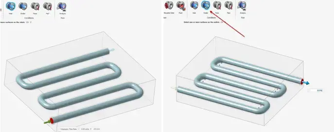
Figure 7: Left Fluid Inlet Conditions and Right Fluid Outlet Conditions
Our outlet conditions for the water will just be ambient pressure and we can click on the opposing face and apply the outlet condition as ambient pressure (Figure 7). The final condition that we want to apply is we want to apply a heat power condition for the enclosure. In our case the outer box will function as a heater, and we will apply total power with a thermal power of about 50 watts. We can do this by clicking on the part boundary condition icon, and then clicking on the enclosure and selecting Total Power as the heat source (Figure 8). Now that our model has been set up, we can run our simulation!
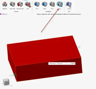
Figure 8: Heat Power of Outer Enclosure
Step 4: Solve Simulation and Visualize Results
Our model is now set up and can be run, to access the run options we can click on the analyze icon and click on the settings to specify our settings for our simulation. In my case I will use a lower resolution as my model’s geometry is relatively basic (Figure 9). However, if I wanted to adjust the resolution, I can easily do that, by adjusting the resolution bar or manually keying in the voxel size. I will also check the compute thermal problem to run the heat transfer analysis. After keying in these settings, I can run my simulation. It should be noted that with the latest release of 2023, the solver has also been enhanced to solve fluid and heat transfer problems even quicker, for more information see the release notes.
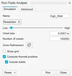
Figure 9: Inspire Fluids Run Options
Our simulation runs quickly, and we are able to visualize our results in our model. One of the first things I want to look at is how the temperature moves through the internal piping. In my case I can see the temperature of the pipe starting at 30F as water enters the piping and then the pipe heats up as water moves through the system (Figure 10).
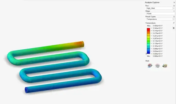
Figure 10: Fluid Temperature Results
Additionally, I want to visualize what happens to the enclosure temperature. One of the cool things about Inspire, is how easy it is to visualize results. In my case, I want to take a look at a cross section of the inside of the enclosure, and I can easily do that in Inspire. I can tell that at the initial entrance the enclosure is much cooler, but at the exit and at locations not near the fluid the temperature is much warmer (Figure 11).
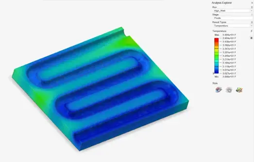
Figure 11: Enclosure Temperature Results
After visualizing the enclosure and the internal piping, I also want to visualize what happens to just the water as it moves through the system. Remember, the water enters the system at 30F and moving at .05 m3/s, I want to see how the water heats up as it moves through the piping. With Inspire Fluids, I can visualize fluids through animated streamlines. This allows me to dynamically see what happens to the water as it moves through the piping. Similar to the solid piping, I can see how the water temperature starts off initially cool and then as it works its way through the piping it heats up until at the exit its much warmer than at the inlet (Figure 12). The results shown here match with my design objectives, and I was able to simulate all of this without having to build a physical prototype!
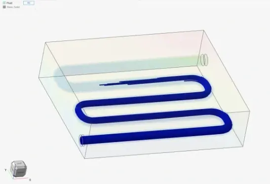
Figure 12: Streamlines of Water moving through Pipe
I hope this blog has illustrated the power and ease of use of conjugate heat transfer in Altair Inspire 2023, and how easy it is to run heat transfer in Inspire Fluids. If you have any more questions about Altair Inspire or any Altair solution, please reach out to us at [email protected]!