
TrueInsight
Siemens/Altair Channel Partner
Menu


Flex Body Generation for Motion, Simplified with Inspire
Flexible bodies can be difficult to manage with assemblies, check out this blog for some tips on how to handle flex body generation built for motion.
Flexible bodies in motion analysis allow for a more accurate analysis in a mechanism where flexibility of a body influences the behavior of the system. Until recently to include this capability in your motion model required exporting your model to Motion View and generating your flex body the “old fashioned way”.
Pre-Inspire Methods:
- Mesh Model in SimLab or Hypermesh
- Define Interface points /ASETS
- Define Solution Parameters for modal reduction
- Solve and review flex results
- Import generated h3d into Motion View
- Identify flex interface nodes and generate motion interface points
- Define joints/forces at interface points
With Inspire generating a flex body is as simple as clicking the FlexBody icon in the motion ribbon.
Why Flex?
For example consider simulating a toggle clamp, until we would rely on joint flexibility for compliance in the model. By its nature a toggle clamp functions by deflecting the linkages. With the addition of flex bodies actuation loads for this mechanism can be simulated with greater accuracy as well as recovering stresses and deformation on the flex bodies.
In this example we see 2 actuator loads:
- Lower force: All rigid bodies with default flexible joints
- Higher force: All flexible bodies with rigid joints the more realistic answer.
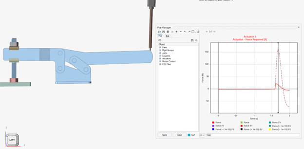
The alternative a model with rigid bodies AND rigid joints would generate a much larger unrealistic load since the only flexibility at that point would be in the solid body contact.
In addition, flex bodies allow stress and strain to be recovered directly from the solution. This is potentially more accurate and a faster workflow than solving for stresses using “analyze part” which extracts loads from a rigid analysis and then solves for stresses separately. However, that is still very useful for optimization load generation.
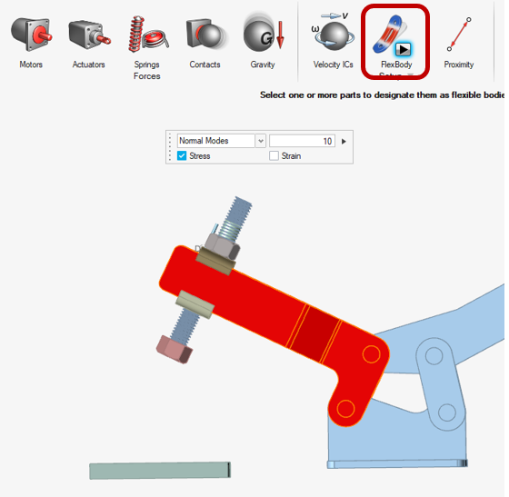
How To?
- Open Inspire version 2022 or greater.
- Define motion joints and forces, couplers etc.. anything entity interacting with the motion body.
- Make sure that part is not part of a rigid group
- Make sure the part does not have contact defined
- Select make Flexible from the motion ribbon, choose the number of modes and stress/strain. The method will mesh and solve immediately.
OR
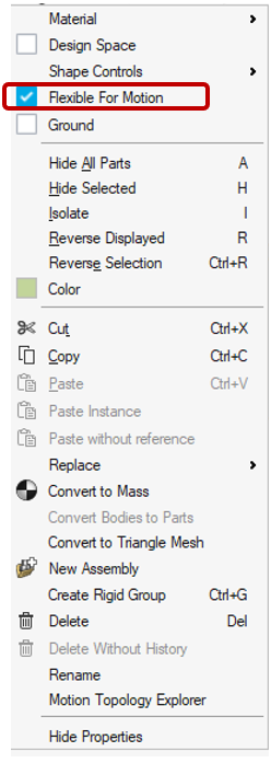
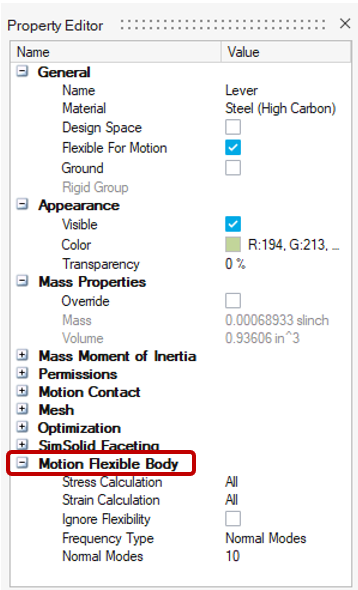
- Right click on the part and choose “Flexible For Motion” which will mesh and solve the flexibility after the motion analysis is initiated. By default ,10 modes will be used and stress/strain not calculated.
After you set up the model for flex bodies you can edit the behavior from the body properties (“F3” right click body in browser or window) . Here you can choose to solve the model with or without flexibility which can be useful when debugging. As well as turn on stress/strain and increase or decrease the number of modes used for the component modes synthesis.
To learn more about flex body generation numerical methods: Altair Help