
TrueInsight
Siemens/Altair Channel Partner
Menu


FEKO Utilities for Efficient Workflows
Learn how to create highly customized models using Altair Feko with the built-in utilities.
Altair FEKO is an extremely versatile tool in the world of electromagnetic design and analysis. This state-of-the-art software allows users to design or import effectively any high frequency devices; from there, a wide range of simulation options are available, such as S-Parameter calculations, far-field and near-field results, surface currents, and much more. Such a powerful tool naturally comes with many layers of complexity, allowing the user to create highly customized models. However, some of these customizations or construction processes may take time away from what really matters: getting high quality, accurate results. Luckily, Altair FEKO is pre-loaded with an impressive set of macros and automations to streamline the simulation stage and reduce the time required to finalize designs.
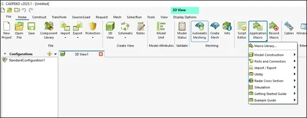
Fig 1. Accessing the Macro menu from the Home banner in Altair FEKO.
Figure 1 above shows how users can access the Macro menu from the Home banner in Altair FEKO, which includes various categories of automation. These include workflows to expedite the creation of model geometry, the setup of ports and connections, various calculators, and more. To showcase the effectiveness of these utilities, we will take a closer look at a few of the tools that many engineers may use quite frequently.
Parameter Sweeps
First, Altair FEKO includes the option for parameter sweeps. This utility allows users to automatically create multiple new models with changes to one or multiple parametric values in the model. These parameters can be physical properties, electrical characteristics, or geometric definitions. For instance, Figure 2 below shows a simple horn antenna with size properties based on the operating frequency (shown as freq in Figure 2). Users can choose the freq parameter to sweep, determine the input type (logarithmically spaced, linearly spaced, manually defined points), and the range of input values for the selected parameter(s).
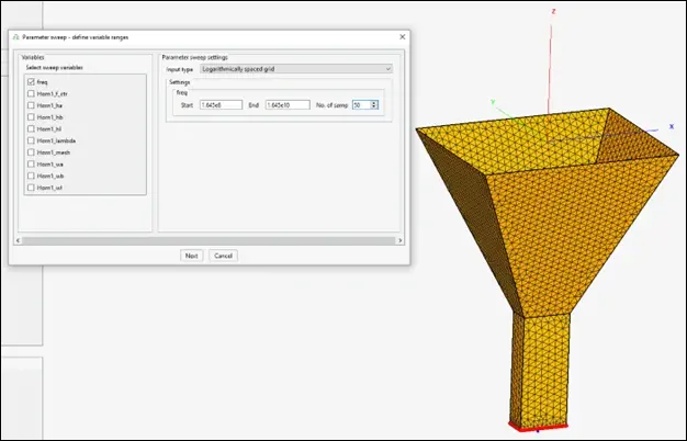
Fig 2. Selection of parameters to sweep using Parameter Sweep utility.
After choosing our variables and their domain, we are ready to begin the model generation. Figure 3 shows the next window of this utility, which allows the user to choose a directory to store each of the outputs. A FEKO geometry file will be generated for each possible combination of input values; in this example, 50 different files would be created, as we set the number of samples for freq to 50. Additionally, users can choose to run the solver for each output file or not. By default, the solver will run, allowing users to compare the entire range of results. This all occurred without the need to manually change a single geometric definition, the models are re-meshed automatically, and each iteration is solved without the need for scripting or monitoring.
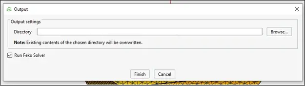
Fig 3. Selection of file output location and option to run FEKO solver in Parameter Sweep utility.
Utility Calculators
Next, Altair FEKO comes with a nice set of calculators, including the modules within the Transmission Line Calculator. Figure 4 below shows the use of this tool to design a microstrip transmission line. This useful window empowers users to quickly turn a handful of design parameters into an accurately designed electromagnetic model.
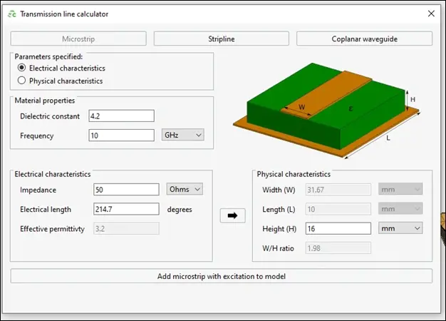
Fig 4. Microstrip Transmission Line Calculator utility in Altair FEKO.
In the microstrip design window, users provide the material properties, choose whether to provide the electrical or physical characteristics, and then calculate the other set of characteristics instantly. Once an engineer is satisfied with their inputs and outputs, this utility also gives users the ability to add the custom microstrip directly to the existing workspace.

Fig 5. Stripline Transmission Line Calculator utility in Altair FEKO.
Similarly, this tool also has options for stripline and coplanar waveguide design, as shown in Figure 5 and Figure 6, respectively. The setup and design for these two types of transmission lines functions very similar to the first. Again, either of these types can be added to the existing model.
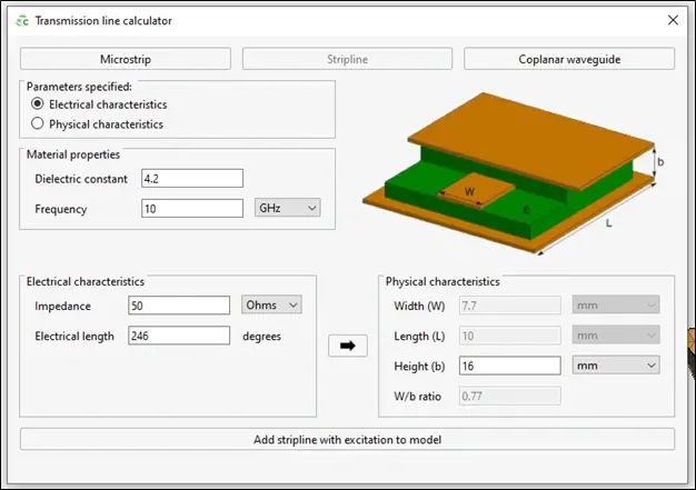
Fig 6. Coplanar Waveguide Transmission Line Calculator utility in Altair FEKO.
Environmental Tools
Lastly, Altair FEKO has tools built in to allow users to manipulate the environment around their designs, as well. For example, Figure 7 shows the input windows for the Create Rough Sea Surface macro. As the name suggests, this automation generates an ocean (saltwater) surface that extends downward infinitely. Users can use the setup screens to define various parameters of the sea surface, including the size and shape of the body of water, as well as the size of the waves in the sea. This is especially useful for simulating devices that may be performing on, immediately above, or below the surface of the ocean.
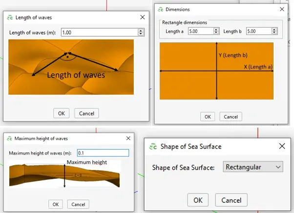
Fig 7. Create Rough Sea Surface definition options.
Figure 8 below shows a typical example of the output from this Create Rough Sea Surface macro. From this point, users have the option to add any further geometry and electromagnetic definitions to the model that are necessary.
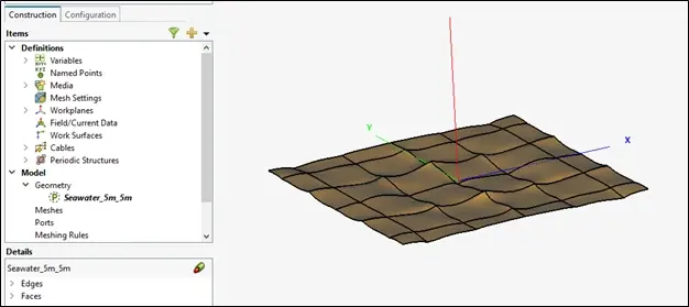
Fig 8. Create Rough Sea Surface output example.
This has only just begun to scratch the surface of the utilities, workflows, and automations Altair FEKO has in place to streamline the design simulation, and analysis processes of electrical engineers. If you would like to learn more about any of these tools, other features within Altair FEKO, or any other tool within the broad portfolio of engineering solutions provided by Altair, please do not hesitate to reach out to us here. As always, be sure to check back often for more information like this, and subscribe to our YouTube channel for even more tips, guides, and walkthroughs.