
Implicit Modeling Ribbon in Inspire 2023
In this post we walk through the steps on using the new lattice creation features in Altair Inspire 2023.
Altair recently released Inspire 2023, and within that release was the brand-new implicit modeling ribbon. If you are unfamiliar with Implicit Modeling, it is a modeling technique, where instead of modeling every vertex with traditional X,Y,Z coordinates, it models it through mathematical equations. As a result of this, you can create complex lattices and unique shapes which would have been traditionally very difficult to do in conventional CAD tools. In today’s blog I am going to walk-through how-to set up a basic implicit modeled part in Altair Inspire 2023.
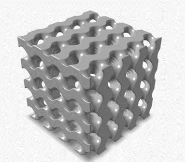 Figure 1: Example of a Lattice Implicit Modeled Part
Step 1: Create Solid Body
The beauty of the new implicit modeling ribbon is its built directly into Altair Inspire, and as many of you are aware Altair Inspire can import various CAD files into it. In our case, I am going to create a solid model of a bracket in Inspire, however, note all the implicit modeling capabilities I am going to show you can work on imported bodies as well. So, feel free to take what I show you in this blog, and try it on some of your own custom imported models into Inspire!
Since I am not importing a model, I need to create a model in Inspire. In my case, I wanted to create a basic bracket, so I created a bracket in the sketch ribbon, and I then extruded it ten inches. Inspire has parametric relations and dimensional parameters, so it makes sketching and creating the 3D model of this bracket very easy. The dimensions of the model are shown in Figure 2, if you want to create the same exact bracket I use in his tutorial!
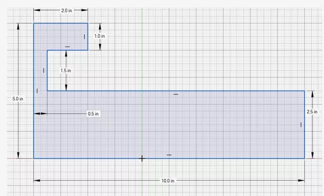 Figure 2: Bracket Cross Sectional Dimensions
Step 2: Create Lattice Body
Once you have either imported a solid model, or created a solid model, we can generate a lattice on the bracket. The advantage of a lattice is it reduces weight while maintaining stiffness and is something that is very useful with more and more designers utilizing additive manufacturing to product their parts. We can navigate to the lattice modeling capabilities by going to the Implicit Modeling Ribbon, shown in Figure 3.
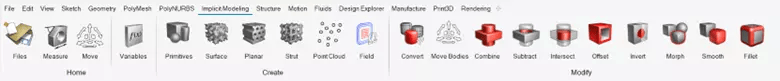 Figure 3 : Altair Inspire Implicit Modeling Ribbon
There are several new options to select in the Inspire Implicit Modeling Ribbon, for more information on each of these new features check out the Inspire 2023 Documentation. However, in our case we are going to focus on creating a surface lattice, so we click on the Surface icon, and then click on our bracket. As soon as we do this, we can select a variety of different types of lattices. Since Inspire 2023 utilizes GPU, we can page through various lattice selections and adjust settings as we see fit (Figure 4).
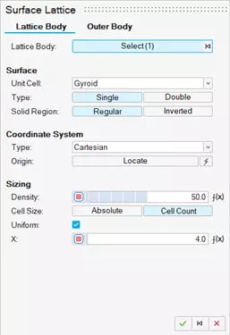 Figure 4: Surface Lattice Options
I ultimately decide to select a Gyroid Double Unit Lattice, with a density and bias of 50. I also make sure it has a uniform magnitude of 4, these settings are indicated in Figure 5. The great thing about Inspire 2023, is there so many different combinations, so if you want to try a different lattice setting, give it a shot!
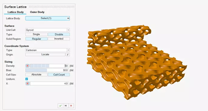 Figure 5: Surface Lattice Options
Step 3: Create Outer Body
At this point, if I wanted to, I could hit the green checkmark on the options setting, and finish my lattice. However, I wanted to create this lattice on the interior of my part, while maintaining the outer surface. So before finishing the lattice, I can click on the outer body tab at the top of the lattice settings and select the overall shell thickness of the outer surface of the bracket. In my case, I want to maintain a surface thickness of .125 inches, so that is the setting I select. Note, I can also apply a transition from the shell surface to the lattice to smoothen the transition, in my case I select a fillet transition with a radius of .04 inch (Figure 6).
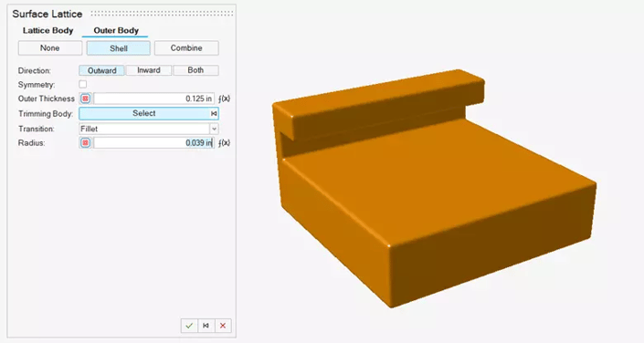 Figure 6: Outer Body Settings
At this point, I have specified all the lattice settings I need, so I can hit the green check mark on lattice box, and I can view my final model. I can see that it maintained the outer surface of my bracket, but if I create a cross section view, I can see the interior and I can see the lattice I just created (Figure 7).
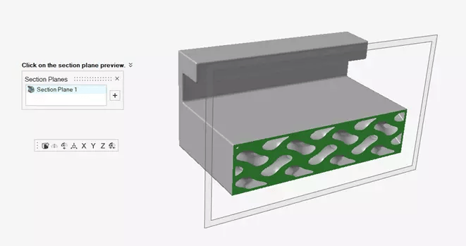 Figure 7: Cross Section View of Final Bracket
I hope this blog has illustrated the power and ease of use of Implicit Modeling in Altair Inspire 2023, and how easy it is to create your own unique lattices. If you have any more questions about Altair Inspire or any Altair solution, please reach out to us!