
TrueInsight
Siemens/Altair Channel Partner
Menu


Blow Molding Simulation using Radioss Solver with AMS
The aim of this study is to explain high-quality time step control i.e. Advanced Mass Scaling (AMS).
The aim of this study is to explain high-quality time step control i.e. Advanced Mass Scaling (AMS), through an example in Altair Radioss solver. Small element sizes normally lead to small time step in explicit solver and tend to be computationally expensive.
Time step control in Radioss using the standard mass scaling option has been there for a long time, but the results had to be checked for added mass and increase in kinetic energy. But with this new high-quality time step control AMS, there is no significant change in inertia effects on translational global acceleration due to non-diagonal mass addition. With AMS accurate results can be obtained with much less computation time. In this study we are performing a Blow molding simulation and comparing the results and computation time with the below 3 options:
- Case 1: No mass scaling
- Case 2: With the Standard mass scaling (/DT/NODA/CST)
- Case 3: The new Advanced mass scaling (/AMS) option
Injection Blow molding Process:
It is a manufacturing process used to create hollow plastic parts by inflating a heated plastic tube until it fills a mold and forms the desired shape. The raw material in this process is a thermoplastic in the form of small pellets or granules, which is first melted and formed into a hollow tube, called the parison. The parison is then clamped between two mold halves and inflated by pressurized air until it conforms to the inner shape of the mold cavity.
Case 1
FE Model Description:
A hollow plastic parison (tube-like) has been formed and clamped into a mold. The two molds are moved in opposite directions with imposed displacement (/IMPDISP), to close the mold. Further air is pumped into the parison to apply pressure load (/PLOAD) (Figure 2), which pushes the plastic out to match the mold. The dimension of the parison is cylinder with 30mm with thickness of 2mm. The dimension of the mold is 207mm x120mm with thickness of 1.0mm (Figure 1), The mold and the parison are modelled with shell elements (/PROP/SHELL) and the contacts are modelled with interface TYPE7.
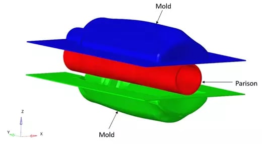 Figure 1 Problem Description for Blow Molding
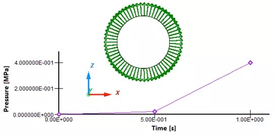 Figure 2. Pressure Load on Plastic Parison
FE Model Details:
Model Units: mm, s, Mg, N, MPa
The mold material: Elastic model (M1_ELAST), below are the details:
- Initial density: 7.8e-9 Mg/mm3
- Young's modulus: 200000 MPa
- Poisson's ratio: 0.3
The plastic parison material: Visco-elastic plastic piecewise linear material (MLAW66), below are the details:
- Initial density: 1e-9 Mg/mm3
- Young's modulus: 4 MPa
Solver Keywords:
- Shell property (/PROP/SHELL)
- TYPE7 interface has been defined between mold and plastic parison with friction 0.7
- Impose displacement (/IMPDISP) is applied to the two molds one in +Z 14.5mm and other in -Z 14.5mm
- Pressure Load (/PLOAD) is applied on the parison inner surface (Figure 2)
- Rigid body (/RBODY) and Boundary condition (/BCS): Using rigid body, two molds have been fixed in all direction of rotation and translations of x and y direction. They are only free in z-direction (translation)
- Using Rayleigh damping (/DAMP) mass and stiffness damping coefficients can be applied to a set of nodes, in our case mass co-efficient of 0.05 is applied to all the nodes
Results:
Case1:
The below (Figure 3) show the plastic strain and von Mises stress on plastic parison for case 1.
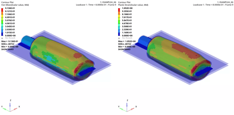 Figure 3 Case 1 Von Mises Stress and Plastic Strain on Plastic Parison
Case 2:
In case 2 we are only adding nodal time step control (/DT/NODA/CST). It is one of the methods for maintaining or increasing the time step, where Radioss will automatically add mass to nodes which have a time step below the specified value, we are using a scale factor of 0.67 and minimum time step of 3.4e-5. The below (Figure 4) shows the plastic strain and von Mises stress on plastic parison.
Keywords
- /DT/NODA/CST/0
0.67 3.4E-05
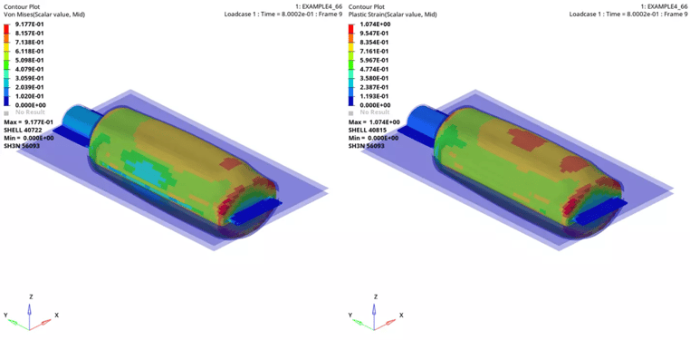 Figure 4 Case 2 Von Mises Stress and Plastic Strain on Plastic Parison
Case 3
In case 3 we are using AMS, it is an elementary time step method that increases the time step to a higher value than the usual elementary or nodal time step. We are using a scale factor of 0.67 and minimum time step of 1.15e-4. The below (Figure 5) show the plastic strain and von Mises stress on plastic parison for case 3.
Keywords
- /DT/AMS
0.67 1.15e-4
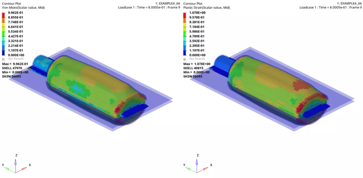 Figure 5 Case 3 Von Mises Stress and Plastic Strain on Plastic Parison
Results comparison: The overall Von Mises stresses and Plastic strains seem to be comparative between all the three cases, however at time 0.4s the plastic strains results of no mass scaling seems to be pretty close with the AMS result and the results with standard mass scaling seem to be off (Figure 6). We can also notice that the internal energy for the standard mass scaling results is getting higher at 0.4s (Figure 7), also there is significant mass addition at time 0s 37.9 % and around time 80s it is around 66% which is quite high (Figure 8).
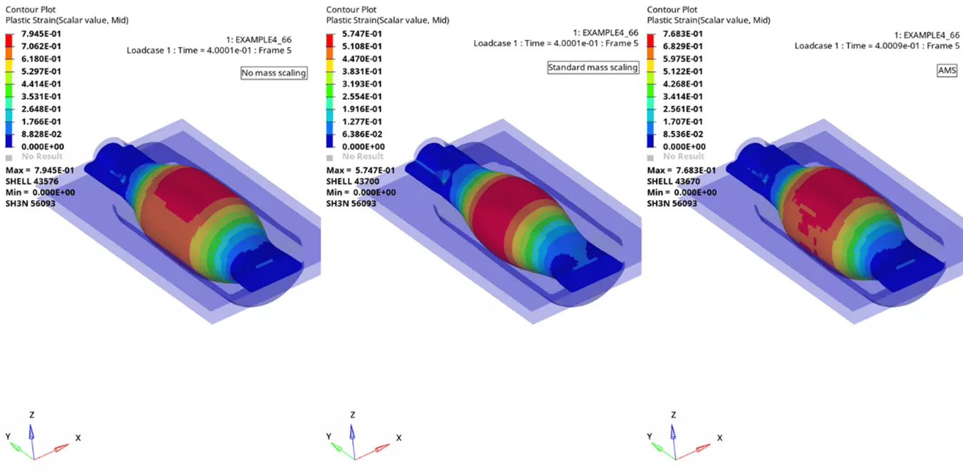 Figure 6. Plastic Strain results comparison at time 0.4s
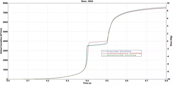 Figure 7. Internal Energy results comparison
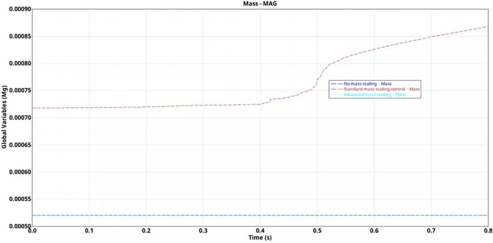
Figure 8. Mass addition
Performance comparison
Below Table 1 shows results comparison for all the 3 cases, in the case using the AMS technique, the CPU time reduced by a factor of approximately 3.8 times and the results were comparable with the no mass scaling, but with the standard mass scaling case the CPU time was reduced 3.5 times but the results were not that good.
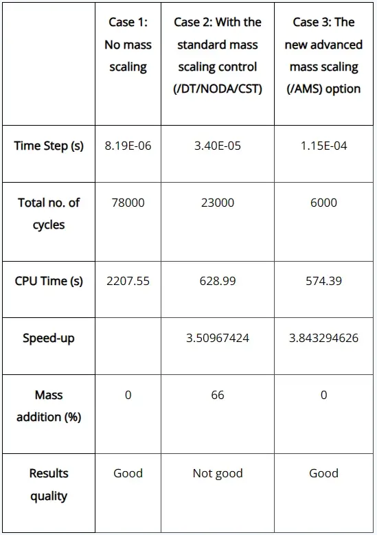
Table 1. Results comparison
Conclusion:
- To obtain a CPU saving factor of about 3.8, the target time step for AMS (1.15E-04) is about 14 times higher than the one with no mass scaling (8.19E-06), the time step for no mass scaling is minimum time step reported by the solver
- Even though the number of cycles for the AMS is very low when compared to the standard mass scaling, but the CPU times are almost the same, the reason being AMS treatment itself is taking some CPU cost
- Standard mass scaling technique can also speed up the calculation by a factor of about 3.5, but the results quality is not good
- In general, AMS technique for a given speed up, gives more accurate results than standard mass scaling.
- The AMS technique does not change the total mass, the mass is added only on non-diagonal terms of the mass matrix and there is no change in inertia effects on translational global acceleration.
- It is applicable to the entire model.
Note:
- AMS technique is highly scalable, large models could show even more significant speed up factors.