
TrueInsight
Siemens/Altair Channel Partner
Menu



Battery Simulation 101: Thermal, Structural, and EM Analysis for EV Battery Packs
How to simulate EV battery packs across thermal, structural, and EM physics using Altair tools.
Electric vehicle (EV) battery packs sit at the intersection of four demanding engineering disciplines: electrochemistry, thermal management and mechanical design, and electromagnetic compatibility (EMC). Each discipline has its own failure modes, its own simulation methodology, and its own software requirements. Simulating all of them accurately, early, and in a coordinated way is one of the hardest problems in EV development today.
This post breaks down the three core simulation domains for EV battery packs, describes the specific engineering challenges in each, and explains how the TrueInsight product line gives engineering teams the tools to solve them before a single prototype is built.
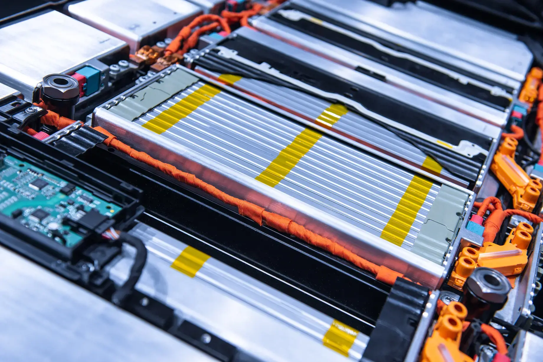
Fig 1: Example battery pack
Why Battery Simulation Is So Difficult
A lithium-ion battery pack is not a single device. It is a hierarchy of cells, modules, and a pack enclosure, each with its own geometry, material properties, and physics. The challenges compound across levels.
- Multi-physics coupling. Heat generated by electrical resistance changes cell impedance, which changes heat generation, which changes mechanical stress in the electrode stack. These effects happen simultaneously and influence each other continuously.
- Scale mismatch. Cell-level electrochemical behavior operates at the micron scale. Pack-level structural loads are in the meter range. Bridging that gap in a single simulation is computationally expensive without the right solver strategy.
- Material nonlinearity. Separator foils, pouch cell casing, and thermal interface materials behave nonlinearly under load, temperature, and aging. Standard linear material libraries do not capture this accurately.
- Regulatory and safety standards. Packs must survive UN 38.3 transport testing, IEC 62660 mechanical abuse, and IP67/69K ingress protection requirements. Each standard creates a distinct simulation scenario that must be set up, run, and reported.
- Short development timelines. EV programs routinely compress battery pack development into 18 to 24 months. Physical testing alone cannot keep pace; simulation must carry the load for the majority of design decisions.
Thermal Analysis: Keeping Cells in the Safe Operating Window
Lithium-ion cells perform optimally between roughly 15 degrees Celsius and 45 degrees Celsius. Outside that window, capacity fades, internal resistance rises, and at the extremes, thermal runaway becomes a risk. The thermal management system (TMS) must hold every cell within that band under all drive cycles, ambient temperatures, and charge rates the pack will see.
The most demanding simulation scenario is thermal runaway propagation. A single cell vents, its neighbors absorb heat, and the engineer must predict whether the event stays contained or cascades through the module. This requires coupled electrochemical-thermal simulation: the cell heat generation rate depends on its state of charge, current, and degradation history, not just its geometry.
Users can address this with CFD solutions like Simcenter FloEFD for pack-level conjugate heat transfer, modeling coolant channels, cold plates, and air gaps simultaneously. Simcenter SimLab accelerates pre-processing of complex pack geometry. Engineers can set up a full transient thermal model of a multi-hundred-cell module, apply drive-cycle boundary conditions, and identify hot spots before the cooling circuit design is finalized. For propagation studies, Simcenter Twin Activate connects a reduced-order cell thermal model to a system-level vehicle thermal management model, letting teams evaluate TMS control strategies without running full three-dimensional simulations at every iteration.

Fig 2: Simcenter FloEFD screenshot
Structural Analysis: Protecting the Pack From Road to Crash
A battery pack mounted under the vehicle floor sees a continuous stream of structural loading: road vibration from 5 Hz to 200 Hz, shock events from potholes and curb strikes, and severe crush loads in a side or pole impact. The enclosure must protect the cells from all of these without adding unnecessary mass, because mass directly reduces range.
Three structural problems dominate battery pack design.
- Fatigue life of the enclosure. Aluminum extrusion frames and welded sheet structures accumulate damage over hundreds of thousands of road vibration cycles. Frequency-response analysis must confirm that natural frequencies do not align with typical road excitation bands, and fatigue life must exceed the vehicle design target, typically 250,000 kilometers.
- Crush and intrusion under impact. Federal Motor Vehicle Safety Standard (FMVSS) 305 and ECE R100 set maximum pack intrusion limits in a crash. The structure must absorb energy and deform in a controlled way that keeps cells intact.
- Cell swelling and internal pressure. Cells expand during charging and contract during discharge. Over thousands of cycles, this swelling load transfers through compression pads to the module frame and pack enclosure. Sizing the compression pads correctly requires coupled mechanical analysis.
TrueInsight provides structural analysis capability through Simcenter OptiStruct for linear and nonlinear static analysis, modal analysis, and fatigue life prediction, and through Simcenter Radioss for high-speed crash and abuse event simulation. Altair SimSolid runs structural simulations directly on CAD geometry without meshing, cutting pre-processing time from days to hours for early-stage design reviews. For topology optimization of the enclosure to meet stiffness targets at minimum mass, OptiStruct's optimization solver identifies the most material-efficient design automatically, giving designers a starting point that physical intuition alone cannot match.
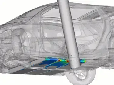
Fig 3: Simcenter Radioss battery impact simulation
Electromagnetic Simulation: EMC and Busbar Design
A battery pack operates at 400 V to 800 V DC and switches high currents through power distribution busbars at frequencies determined by the inverter switching rate, typically 5 kHz to 20 kHz. This makes the pack a significant source of conducted and radiated electromagnetic interference (EMI). At the same time, the battery management system (BMS) contains sensitive analog measurement circuits that must not be disrupted by the switching noise generated nearby.
Two electromagnetic problems are critical at the pack level.
- Busbar current distribution and inductance. Uneven current distribution across parallel cell strings causes some cells to discharge faster than others, shortening pack life. High busbar inductance creates voltage spikes at the inverter that stress insulation and switching devices. Both require three-dimensional electromagnetic (EM) field simulation to predict and correct early in the design cycle.
- Radiated EMI from the pack enclosure. Gaps, seams, and connector penetrations in the enclosure act as slot antennas. At inverter switching frequencies and their harmonics, these can radiate fields that violate CISPR 25 limits and interfere with in-vehicle communications systems.
TrueInsight addresses electromagnetic simulation with Simcenter Feko for full-wave EM analysis covering radiated EMI prediction and shielding effectiveness evaluation, and with Simcenter Flux for low-frequency magnetostatic and eddy-current analysis of busbar geometry. Feko can model the entire pack enclosure as an antenna problem, identify which apertures contribute most to radiated emissions, and guide shielding and gasketing decisions before manufacturing tooling is committed. Flux accurately resolves current density distributions in multi-layer busbar stacks and predicts inductance values that feed directly into circuit-level models.
Bringing the Physics Together
The most dangerous battery failure modes involve multiple physics interacting at once. A cell that overheats swells; a swollen cell changes contact resistance and generates more heat. An enclosure that cracks from road fatigue allows moisture ingress, which degrades isolation resistance and triggers a ground fault. These coupled failure sequences are missed when thermal, structural, and EM analyses run in isolation.
The Simcenter HyperWorks platform, provides a unified simulation environment where CFD thermal results feed into structural analyses as temperature-dependent material properties, and where EM shielding studies reference the same geometry as the structural model. This reduces manual data transfer errors and makes coordinated multi-physics simulation practical within a compressed program schedule.
Common Pitfalls in Battery Pack Simulation
- Under-resolved thermal models. Using a uniform heat generation rate across a module instead of per-cell values based on actual resistance distributions produces optimistic temperature predictions that do not match test results.
- Ignoring weld and joint compliance. Treating welded enclosure joints as rigid in a structural model overstates stiffness and underestimates fatigue damage at the heat-affected zone.
- Skipping EMI early. EMC simulation is often deferred to late in the program when geometry is fixed. Aperture locations and cable routing decisions made early in packaging have the largest impact on radiated emissions; simulating them late means expensive design changes.
- Single-physics acceptance criteria. Approving a cooling design based on thermal results alone, without checking the structural consequences of the resulting cold plate geometry, leads to conflicts discovered only during integration.
Work With TrueInsight on Your Battery Pack Program
If your team is designing an EV battery pack and needs to build a credible simulation workflow for thermal, structural, or EM analysis, our engineers can help you select the right tools for your pack architecture and program schedule.
Contact TrueInsight to schedule a technical discussion or request a demonstration of Simcenter battery simulation capabilities.