
TrueInsight
Siemens/Altair Channel Partner
Menu


5 FEA Pitfalls and How Altair Tools Help Avoid Them
In this post, we look at 5 pitfalls for FEA users and how to avoid them using Altair solutions.
Even experienced FEA analysts can fall into common traps that compromise accuracy, inflate costs, or slow down the design cycle. Fortunately, Altair’s suite of FEA tools, including SimSolid, SimLab, and OptiStruct, offer built-in safeguards and features to help engineers avoid these pitfalls. In this post, we’ll cover five FEA pitfalls and explain how Altair software helps prevent them with automation, speed, and smarter workflows.
1. Over-Meshing or Under-Meshing the Model
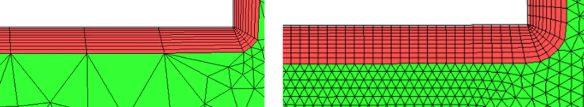
Fig 1: Examples of different mesh coarseness
The Pitfall:
Meshing is one of the most critical, yet error-prone steps in traditional FEA. Too fine a mesh wastes time and computing resources, while too coarse a mesh can miss critical stress concentrations or fail to capture real-world behavior.
Many times, users believe that finer meshes will always yield more accurate results. Depending on the analysis, this can be true, but many times it ends up increasing solve times without a proportional improvement on accuracy. This is called mesh convergence and getting a good balance on mesh size to accuracy can have a big impact on time to results.
The Altair Solution:
- Altair SimSolid eliminates meshing altogether by using a meshless, adaptive solver. Engineers can import CAD geometry and skip the steps of simplifying geometry and creating a mesh to move straight into setting up the study. This allows users to get accurate results within minutes, making it ideal for early-stage design.
- For users who need mesh control, Altair SimLab provides automated meshing templates and local refinement features that ensure quality without excessive manual tuning. It’s a great balance of ease of use and advanced meshing capabilities.
- Altair HyperMesh also provides advanced mesh diagnostics and quality checks for users who need complete control over mesh generation. This is ideal for users that need advanced mesh control.
2. Ignoring Contact Definitions or Improperly Defining Interactions
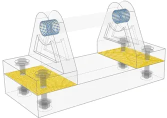
Fig 2: Model with Contacts defined
The Pitfall:
Overlooking contact definitions between parts can result in unrealistic simulations. Many failures in assemblies occur at interfaces; like bolts, welds, and bonded surfaces, yet these are often misrepresented or skipped due to setup complexity.
Without accurate contacts, many issues could arise like: Loads applied to one part may not transfer correctly to another, Over/Under-constraining the design, or in thermal designs it can affect thermal resistance and heat conduction.
The Altair Solution:
- SimLab simplifies contact modeling with automated detection of bonded, sliding, or frictional contacts. It also supports contact groups, making it easier to apply consistent definitions across multiple parts.
- OptiStruct (part of Altair HyperWorks, and included in Altair SimLab as well) includes advanced nonlinear contact capabilities, including large sliding and surface-to-surface interactions, perfect for simulating real-world behavior in mechanical assemblies. With HyperWorks, users can also use the Connector Browser to view and modify connectors in the current model.
- In SimSolid, contact conditions are automatically inferred based on CAD assembly data, drastically reducing setup time without sacrificing accuracy. SimSolid also offers the ability to manually apply contacts as well.
3. Applying Incorrect or Oversimplified Boundary Conditions
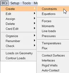
Fig 3: Boundary condition options
The Pitfall:
At times, engineers will simplify boundary conditions in order to speed up setup and solve times. Boundary conditions define the structural load path and how the design interacts with its environment. If you constrain the model unrealistically, you distort how forces are transferred between components. This means product decisions can be made on less than accurate results.
One example of this would be replacing multi-body supports with a single-point constraint to save time and avoid potential solver issues, but this can also lead to inaccurate load path through the model.
The Altair Solution:
- SimLab offers drag-and-drop boundary condition application, this allows users the ability to reuse realistic loading conditions across multiple studies. SimLab also allows users the ability to apply unique loads like sensor or motion studies, remote and multi-point loads or bolt pretension.
- OptiStruct offers advanced contact and constraint definitions including frictional contacts, gasket compression and flexible bushings. It also supports a wide range of realistic loading types: temperature fields, pressure distributions, inertia, preload on bolts, and more.
- With SimSolid, engineers can apply loads and constraints directly to CAD geometry, not meshelements or mesh nodes. Not being dependent on mesh means users can iterate very quickly to see the impact of design changes. It’s also aware of assembly-level interactions, so when a constraint or load is applied it propagates through the relevant contact regions.
4. Skipping Validation or Failing to Check Simulation Assumptions
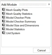
Fig 4: Validate Group options in HyperWorks
The Pitfall:
FEA is a predictive tool, but its accuracy depends on correct inputs. Many errors stem from skipped validation steps or unchecked assumptions in material data, mesh quality, or solver settings. Unvalidated assumptions can produce error-free and clean looking results that may or may not be accurate.
We hear the term “Garbage In, Garbage Out” often, especially when talking about simulation tools. This is more than just a catchphrase though, it’s an incredibly important concept to understand. It essentially means the less accurate the setup of your study is, the less accurate your results are going to be.
The Altair Solution:
- SimLab’s process automation allows users to embed validation checks, like displacement limits or maximum stress thresholds, into the simulation workflow. It also allows users to save validated assumptions as templates, which can be standardized across an organization.
- Altair’s multiphysics tools mean users can incorporate many design variables simultaneously, allowing users to understand how one variable might impact another. The multiphysics platform also makes it easy to cross-validate results. For example, a structural analysis in OptiStruct can be cross-checked with thermal results from SimLab to ensure accuracy. HyperWorks also includes Model Checker, which can be used to configure solver validity checks, modify and create new checks and corrections.
- SimSolid enables real-time "what-if" validation through geometry-based simulation that updates results instantly with design changes. Because this can be done with nearly instant feedback, users can try different constraints or load assumptions rapidly.
5. Spending Too Much Time on Geometry Cleanup
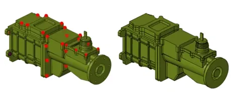
Fig 5: Before and After Defeaturing
The Pitfall:
Traditional FEA workflows often require significant time spent cleaning or defeaturing CAD models. Steps like removing fillets, holes, or small parts are needed before meshing is considered. This can be one of the most time-consuming, frustrating, and error-prone parts of the process.
Meshing with most simulation tools comes with some built-in requirements to get a usable result. Examples of these requirements could be: Watertight geometry, reasonable aspect ratios and clean surface connectivity. To meet those requirements users must: Resolve part intersections, remove holes or logos or manually stitch/remap edges. At times, the process of defeaturing can take more time than the simulation itself.
The Altair Solution:
- SimLab automates defeaturing to remove holes, rounds or small faces based on size or type. Geometry checks for intersections and stitching allows users to quickly identify and resolve issues. Because of its automation features, it lets users create reusable templates for recurring cleanup tasks.
- With HyperMesh, users can perform automatic cleanup operations on selected surfaces using the Defeature Batch tool. By batching these operations users can save a lot of time and effort spent defeaturing models.
- As mentioned multiple times in this post already, SimSolid bypasses this step by allowing engineers to simulate directly on full CAD assemblies, even with complex geometries or imported parts. No geometry simplification is required.
Avoiding common FEA pitfalls is critical for engineers who want to produce reliable, efficient simulation results. Things like over- or under-meshing, inaccurate contact definitions, oversimplified boundary conditions, unvalidated assumptions, and excessive geometry cleanup can compromise the integrity of an analysis
These missteps can lead to wasted time, misleading conclusions, or costly design errors that only surface later in prototyping or production. By addressing these pitfalls with smarter workflows, better inputs, and a focus on physical realism, engineers can reduce rework, accelerate design cycles, and make more confident decisions based on simulation. To learn more about the Altair solutions, don’t hesitate to reach out to us.