
TrueInsight
Siemens/Altair Channel Partner
Menu



How to utilize the Auto Contact tool in Simcenter SimLab
Check out this tutorial on how to utilize the Auto Contact feature in Simcenter Simlab
Simcenter Simlab is a Multiphysics tool, that can run numerous parallel simulations. One of the most popular simulation types run in SimLab are structural simulations. Anyone who has run a structural simulation recognizes that for assembly analysis, it is imperative to represent the contact behavior of interacting parts to obtain an accurate result. One of the drawbacks of contact setup in external tools is often times it becomes a tedious process that requires the user to zoom, rotate, and select faces and do this repeatedly. In many cases contact setup can become something that will extend your preprocessing time. Though SimLab has a way around this, with its auto detection tool. In today’s blog I am going to step you through how to utilize the automatic contact detection tool!
Manual Contacts in Simcenter SimLab
Like many other FE tools, SimLab has the ability to specify contacts manually, where a user can click on individual faces and then specify the type of contact. The challenge in this is that the more parts you have, the more tedious this process becomes. For example, say you have a single bolted joint that touches at least three parts: The bolt shank, the clamped faces and a washer. Doing this by hand will become tedious as it requires multiple face selections and will be a drawn out process. However, it should be noted you can manually specify contacts in SimLab and it’s shown in Figure 1.
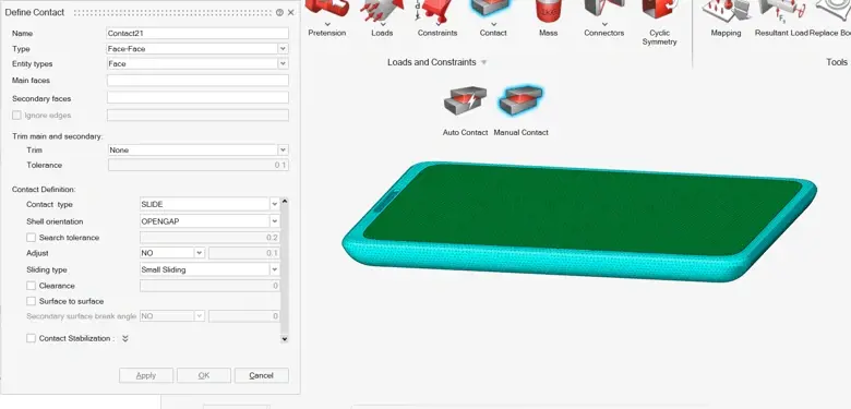
Figure 1: Manual Contact Selection in Simcenter SimLab
Automatic Contact Selection in Simcenter SimLab
So, let’s take a look at the automatic contact selection tool. The automatic contact selection tool can be found under the Analysis tab and then clicking on Contact and then Auto Contact (Figure 2).
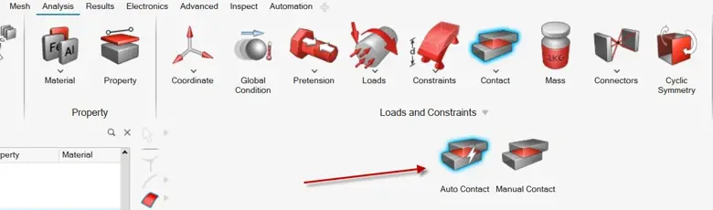
Figure 2: Location of Auto Contact in Simcenter SimLab
Rather than selecting face pairs one at a time like the manual contact selection, you select the components you want checked and then provide a proximity distance. Anything within that tolerance gets mapped with a contact. It’s important to note that the tolerance distance you select is more important than most users realize. If the tolerance is set too tight, you will miss real contacts because you may be missing CAD gaps. Additionally, if you specify too loose a tolerance, you may end up having false contacts that don’t make any sense.
My rule of thumb is to use the manufacturing tolerance you have for your parts and set that as your initial contact tolerance. If needed increase that tolerance if there are larger known CAD gaps. The proximity tolerance selection is shown in Figure 3.
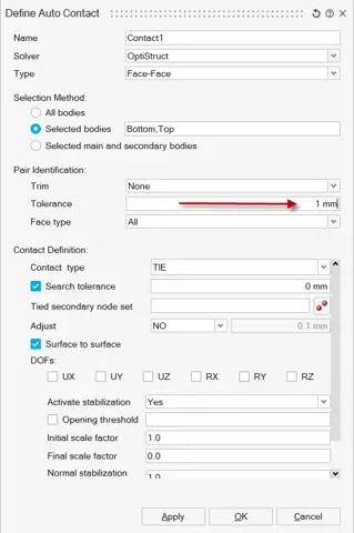
Figure 3: Tolerance Setting in Auto Contact
In addition to setting the tolerance for auto contact, there are a number of pertinent contact types that accurately model the interaction between parts, these can also be selected in the auto contact tool. Here is how to define the different type of contacts:
- Tie: A contact the bonds surfaces together permanently. There is no relative motion, sliding or separating allowed anywhere on the contact interface.
- Slide: Allows contact behavior for surfaces to slide against each other in the contact plane with either friction or no friction governing the contact behavior. This is the real contact type, so if you have parts that separate, close or slide, this is the contact to utilize.
- Stick: Prevents sliding between contacts but still represents normal-direction contact stiffness. Effectively the contact surfaces can separate if pulled apart and compress if pushed back together. Commonly used for joints.
- Freeze: This is functionally identical to a tie contact in Optistruct, there is zero relative motion. However, it accomplishes this through a penalty-based contact using stiffness, where as a tie contact obtains zero relative motion through lagrange multipliers.
- Contact Params: Instead of using a preset contact, like the above contacts, this tells the solver to pull the contacts actual behavior from a PCONT card, which contains the frictional coefficient, stiffness and clearance settings. This is when users want more control over the contact physics rather than the fixed preset.
- Cohesive: Models a cohesive/adhesive bond with a traction-separation law, including damage initiation and evolution, i.e., the bond can degrade and fail under load rather than being perfectly rigid or perfectly free. It's built for adhesive joints or delamination-type problems, and it saves you from having to explicitly mesh cohesive elements to get that behavior.
With the ability to automatically define your contact quickly and then being able to set advanced contact behavior, there really is no reason to be utilized the old classic manual contact. Utilizing the auto contact tool will save you time and pain vs the classic manual selection method.
One of the final great things about Simcenter SimLab, is after you generate the contacts via the Auto Contact tool, you can easily visualize all contacts with the visualization tool. This tool enables users to make sure all appropriate contacts have been defined. The contact browser can be found by right mouse button clicking on contacts in your solution tree and then selecting the option “review” (Figure 4).
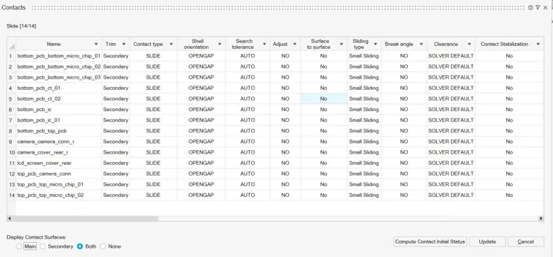
Figure 4: Contact Browser for Auto Contact
Within the contact browser, you can change any of the specific settings for all the contact settings you have created. Also, by clicking on any contact, you can visualize that specific contact location and if the defined contact makes sense. Through, the use of the auto contact tool in Simcenter SimLab, users can speed up their preprocessing time while also still being able to select advanced contact settings like you would with the manual contact selection tool. As I indicated above, there really is no reason you shouldn’t be taking advantage of the auto contact tool today, so give it a shot!
To learn more about Simcenter SimLab or any other Siemens product, please contact us here at TrueInsight!