
TrueInsight
Siemens/Altair Channel Partner
Menu


Altair SimSolid: Working with Contacts
Dive into some of the common issues with creating connections with analysis and how SimSolid can help smooth that process.
Altair SimSolid is a structural simulation that runs its calculation based on original CAD geometry. The geometry does not need simplification like with traditional structural analysis packages because SimSolid does not use a mesh to run its calculations.
In addition to static structural analyses, SimSolid can run other analysis types such as modal, dynamic, non-linear, and thermal. SimSolid is rich with connections and contacts often needed when working with large assemblies like bonding, sliding connections, separating connections, and more sophisticated connections like welds and adhesive connections. In this blog, we will review some popular connections available in SimSolid.
Common Challenges with Creating Connections in an Analysis
Establishing connections is one of the most important aspects of setting up an analysis in most simulation software. Depending on the complexity of the model, it can also be a time-consuming step of the analysis setup process because of the need to inspect all contacts individually as a best practice.
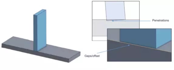
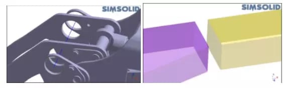
Another aspect of setting up connections is issues related to model geometry. Looking at the picture below, the model appears to be in proper contact, but in reality, it could have very small gaps or overlaps. We would need to zoom in quite a bit to detect these types of issues. If missed, these issues could throw off your setup or cause errors in your simulation down the line. Normally, issues like this need to be addressed in the native CAD software before proceeding with the Simulation.
So now that we have an idea of what some of the challenges are when working with contacts, let’s take a look at what working with connections in SimSolid could look like.
The overall benefit of working with SimSolid is that we can help alleviate some of the challenges and tedium of setting up traditional connections. A utility we find exceptionally useful is automatic connections.
When importing your model into SimSolid, we are prompted to detect and establish contacts automatically. This utility has the capability of creating thousands of connections in a matter of minutes.
Another useful capability of SimSolid is that it can resolve relatively small gaps and overlaps. In the picture below, we can see examples of how different overlaps and gaps can be handled using SimSolid.
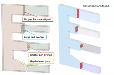
For penetrating bodies, it will project to where the interference will intersect and generate contacts at those locations. For gaps like on the bottom example, the tool will decide as to what side of the gap to apply the contact to.
Overall, SimSolid will tend to accept imported geometry as-is without the need for tedious cleanup and repairs. This is true for most of the smaller gaps and overlap issues typically encountered with CAD models and is another impressive aspect of this tool.
If you do have a model with extreme gaps and overlaps relative to the scale of the model or design, it’s still best practice to resolve these instances.
Contact Condition Types with SimSolid
Before we look at a demonstration of SimSolid, you should first know the basic types of contact conditions that can be created.
The following types of connections are available. (The graphics area in SimSolid will also give you visual feedback as to the types of connections by using a color code.)
- Bonded contact conditions are exactly as they sound. This connection type is used to contact parts that act as if they were bonded or stuck together. Loads between parts are fully transferred through the connection and bonded components never separate from each other during the analysis.
- Sliding without friction allows parts to slide relative to each other and doesn’t allow penetration or the separation of the contacting surfaces. This contact type also doesn’t take friction into account.
- If you do require more advanced contact types, separating connections can be used when parts need to be partially or completely separated from each other. This time, friction is taken into account and the friction coefficient defines the sticking, sliding threshold of the parts involved in the connection. This is a non-linear contact that will take more time than simple bonding or sliding contact types.
- Separating/closing connections are almost identical to separating contacts except that existing gaps can also close.
- Disabled contacts act as if they were disconnected, meaning they may separate from each other or overlap into each other under load. Also, applied forces do not transfer through these disabled contacts.
Types of Connections
Bolted Connections
Bolted connections in SimSolid require the imported model geometry to include the actual bolts and fastener geometry from the CAD model. Bolted connections are not treated as virtual components, and since SimSolid does not require meshing, the extra details included with the fasteners will not heavily set back your computer’s calculation resources.
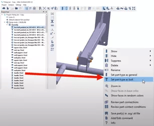
On the contrary, you will actually increase the accuracy of your structural response of the model. Because of this, when assigning bolted connections, the geometry has to make sense and there has to be appropriate geometry for the correct contact for the head and of the shank contacting surfaces of the bolts. The flexibility of specifying accurate bolt definitions in SimSolid is that we can apply force conditions to the bolt with traditional force loads in the study, or you can specify specific bolt or nut tightening conditions.
We can tighten bolts or nuts by specifying the number of turns, entering a target torque value, or by entering a target axial force on the geometry.
Welded Connections
Weld connections are specialized connections used to define specific weld properties in an analysis. When applying welded connections, the assumption in SimSolid is that the weld is perfectly created and perfectly bonded.
Welded connections can be used together with other types of standard connections such as bonded or sliding connections. There are three types of welded connections:
- The Spot Weld is defined by a spot diameter and geometric location as a point between two parts in the analysis space.
- The Laser Weld is defined by a laser weld width and a line created by two points we will specify for coinciding parts in the analysis space.
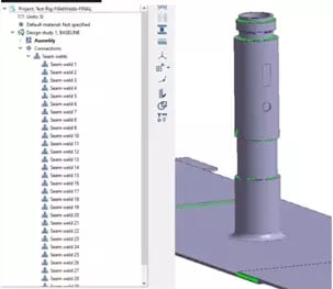
- The Seam (fillet) Weld is defined by a seam weld selection size along existing edges between existing parts in the model. We can also specify intermittent welds with this tool.
Virtual Connections
Virtual connectors are a good alternative for transferring loads from one component to another when the components are missing in the model. The downside to this is that results will not be visible on these virtualized connectors and anything that is specified as virtual in the calculation will behave perfectly rigid during the structural response of the model.
Another downside is that virtual connectors may cause heightened or localized stress connections around the areas of the joining components.
Virtual Pins
One of the easiest virtual connections to use is virtual pins. Virtual pins will connect coaxial cylindrical faces in your model. They can be specified as either rotating, acting as a hinge, or bonded locking the components that are connected in place.
Virtual Rivets
Virtual rivets connect multiple stacked parts with a rivet of a specified diameter by picking the location on a part face in the analysis space. The rivet will be assumed to pass through the stack components.
General Virtual Connector
The general virtual connector will connect specified components rigidly between either faces or specified spots on the model as if a rigid component or epoxy connecting the parts.
Remote Mass
The remote mass capability will connect the specified face or spot on the model to a hypothetical or virtual model of a specified mass. This is useful to help represent missing geometry in your analysis.
Adhesive Connections
Adhesive connections in SimSolid must be modeled with a deliberate gap in between entities that will be connected. This is used to figure out the thickness of the adhesive in the software. If the adhesive's faces are coinciding or touching, SimSolid will detect touching faces and display a warning message.
There are two ways to establish adhesive connections in SimSolid: converting an existing contact or by using reference geometry.
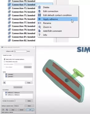
To convert an existing contact to an adhesive, right mouse click on the connection you want and select ‘apply adhesive’ to the context menu. There will then be a popup window to specify the material of the adhesive to finish the definition. Applying an adhesive in this way will apply the adhesive to the full contacting region.
If you would like to have more control as to where you apply the adhesive, you must create an adhesive condition using the existing reference geometry method. For this, we have to make sure that we have modeled a tubular or cylindrical geometry that represents the adhesive as if it were piped in the desired location of the model. That will determine the thickness of the adhesive surface area.
This tubular geometry must also interface a small amount with the two faces you want to connect. We can see an example of this below:
SimSolid will then extract the centerline of the cylindrical tube to create the adhesive region. The thickness of the adhesive will be determined by the spacing between the two parts.
That wraps up Altair SimSolid and working with contacts. To learn more about SimSolid or any other Altair product, please contact us.