TrueInsight
Siemens/Altair Channel Partner
Menu


Altair SimSolid and Welded Features
Altair SimSolid has specialized tools for including welded features in your design analysis. This post talks about the types of welds and how to use them.
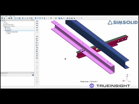
Altair SimSolid is a meshless simulation tool, that is ideal for running quick simulations during the design phase. Because it doesn’t create a mesh and has no need to simplify geometry, running simulations on large assemblies is also a strength of SimSolid. With many designs, large or small, welds are commonplace, and understanding how they react under loads is just as important as the assembly itself.
With Altair SimSolid, users can run strength analysis to understand the strength of welded joints under various loads, understanding how welded parts will deform under loads and assess how long a welded structure can withstand repeated loads before failure. In this post, we will look at the different weld options in SimSolid, how to set them up and how to interpret the results of a simulation study using welded features.
Types of Welds in Altair SimSolid
Altair SimSolid offers multiple weld types to cater to different engineering needs. These include:
Spot/Laser Welds
A small circular shape or spot is created to connect two parts. Used primarily in sheet metal applications, spot welds are ideal for modeling car bodies, electronic enclosures, and other similar structures.
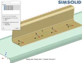 Fig 1: Spot Welds in SimSolid
Seam/Fillet Welds
These are most common when joining pieces along a continuous seam. With SimSolid, these welds are created as a solid body, and the size and length can be defined by the user. Popular applications would be exhaust systems, steel drums or radiators.
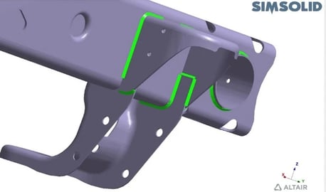 Fig 2: Seam Weld in SimSolid
Including Welds in your Assembly
SimSolid makes the creation of weld features incredibly easy. Users just need to find the Connections identifier from the Project Tree, choose what kind of weld they need to create, and add the details in the associated menus.
Creating Spot/Laser Welds
- Find the Create Spot Weld Icon, indicated below.
- Identify the location of the Spot Welds, number of spots on the line and how large the spots need to be.
- Click OK.
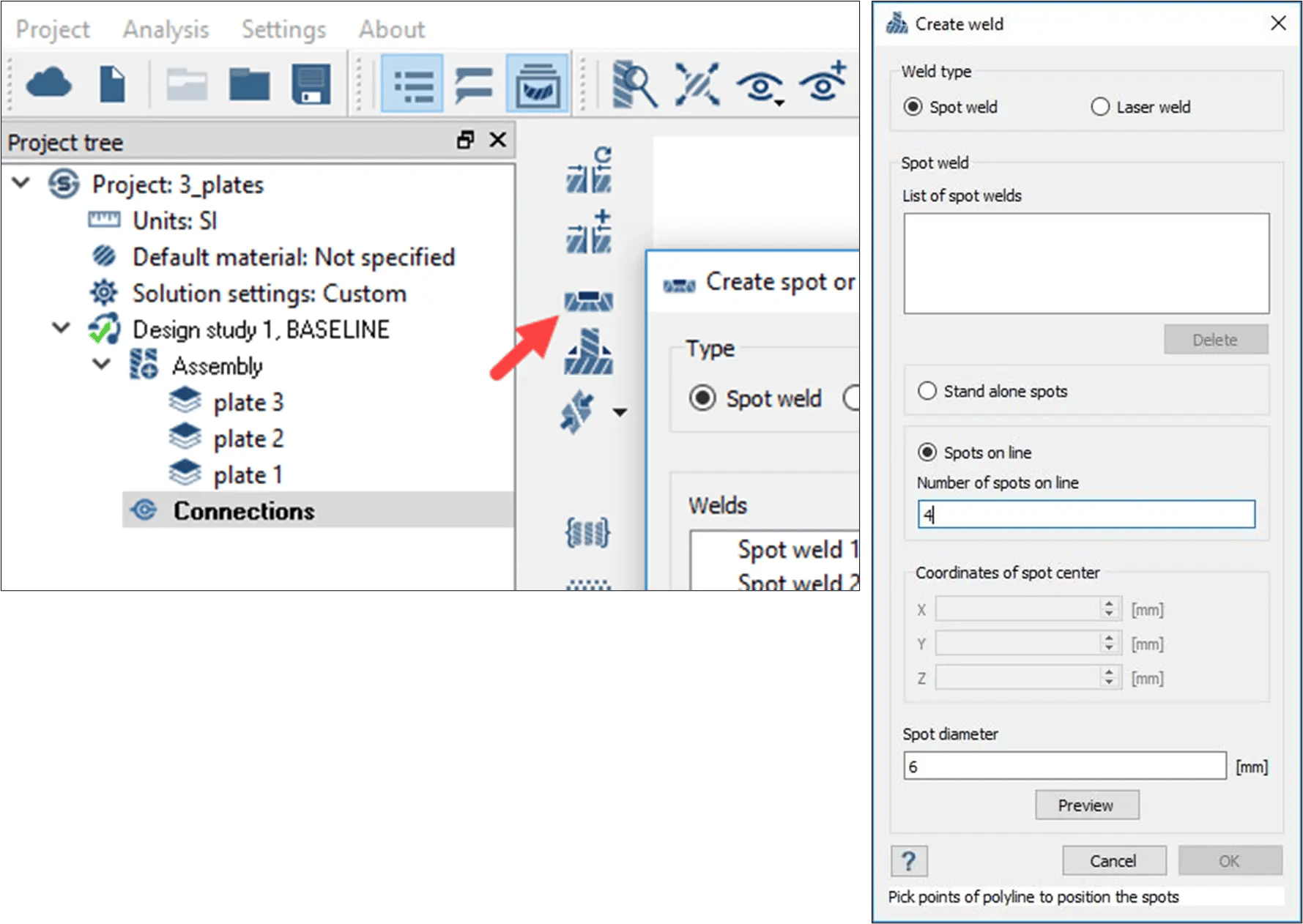 Fig 3: Left: Create Spot Weld Icon Right: Spot Weld menu
Creating Seam/Fillet Welds
With Seam/Fillet welds, users have a few options. Create welds from Solids, create welds from master and mate parts, create welds from lines or edges, or group weld for multiple parts. Like the Spot Weld, users would find the Create Seam Weld icon, which will populate a menu to guide the user in the next steps.
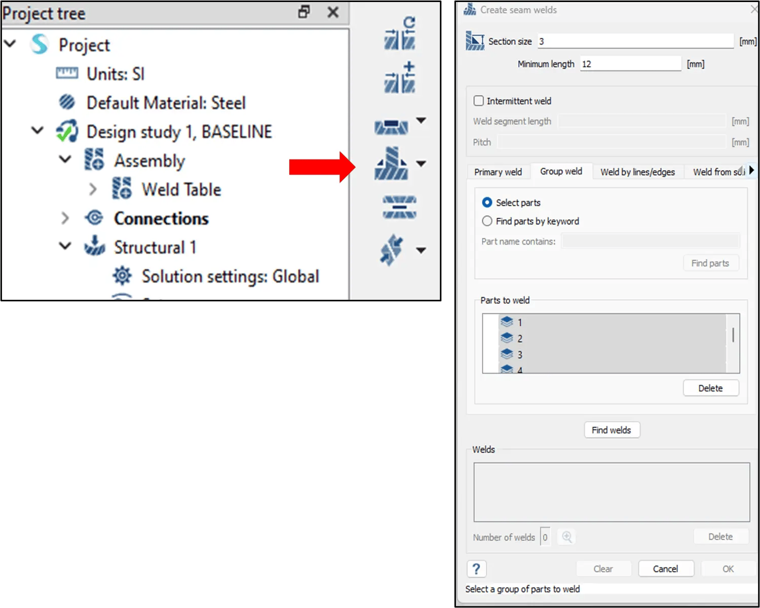 Fig 4: Left: Create Seam Weld Icon Right: Seam Weld menu
Weld from Solids
- Find the Weld from Solid tab in the Create Seam Menu.
- Manually select solids to be converted OR find parts by Keyword by searching the term “Weld”.
- Click Find Welds to generate list of welds to be created.
- Confirm welds were identified correctly and Click OK.
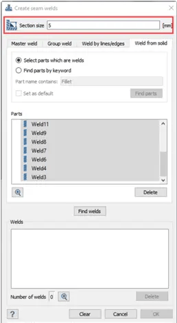 Fig 5: Create Seam Weld from Solid
Welds from Lines/Edges
- Find the Weld from Lines/Edges tab in the Create Seam Menu.
- Manually select lines or edges in your design
- Click Find Welds to generate a list of welds to be created.
- Confirm welds were identified correctly and Click OK.
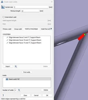 Fig 6: Create Seam Weld from Lines/Edges Menu
Welds from Master and Mate
- Find the Weld from Primary tab in the Create Seam Menu.
- Manually select the Primary Part in the Primary Part Field.
- Manually select the Mate Part in the Secondary Part Field.
- Click Find Welds to generate a list of welds to be created.
- Confirm welds were identified correctly and Click OK.
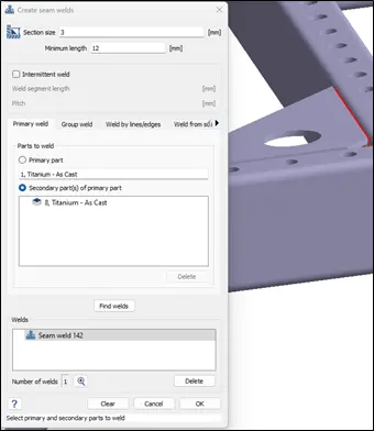 Fig 7: Create Seam Weld from Master/Mate (Primary) Menu
Group Weld for Multiple Parts
- Find the Group Welds tab in the Create Seam Menu.
- If you want to manually select the parts to be included, choose the Select Parts button, and identify the parts you want welds to be created between.
- Users can also find parts by Keyword, similar to the Weld from Solids option.
- Click Find Welds to generate a list of welds to be created.
- Confirm welds were identified correctly and Click OK.
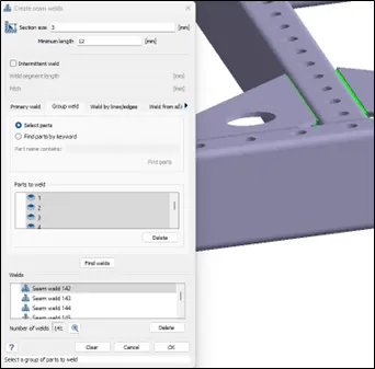 Fig 8: Create Seam Weld from Group Weld Menu
Postprocessing Results on Welded Features
SimSolid offers the standard post processing results from Images with gradients for Stress, Displacement, Strain and Factor of Safety. It also has some results tools that are specific to welded structures.
Pick Info
The Pick Info results option allows users to get specific results based on one point, multiple points, or faces on the model. In this case, a user can find specific stress or displacement data for potential weak points in a weld.
Once users, click the Pick Info icon, located below the Result plot icon, seen below in Fig 9, they would choose the response they are looking for, then click on the point of the weld that is of interest to them.
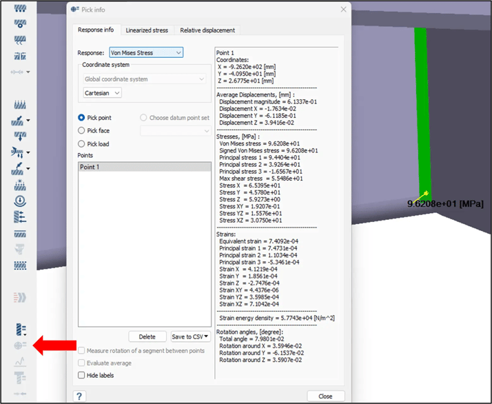 Fig 9: Pick Info icon location and menu options
Weld Force Reactions Table
This option lets users display a table of weld forces (or fatigue results) for those that are included in the study. To display this information, users should find the Weld forces icon on the left-hand side, near the bottom as shown in Fig 10. Once that menu is populated, users can choose the result they want from the tab options and click Evaluate. This will populate the table of results for all Welds in the study. This table can now be exported as a .CSV file if needed.
 Fig 10: Weld Forces Table Icon and Menu
Hopefully this has helped you see some of the added benefits of using Altair SimSolid with welded structures. Check out the video below to see a walkthrough of these features as well.