
TrueInsight
Siemens/Altair Channel Partner
Menu


Tips and Tricks in Altair PSIM
Learn more about how Altair PSIM can make your workflow more efficient with these tips and tricks.
Altair PSIM is the number one solution when it comes to circuit simulation. This software allows engineers to efficiently and accurately model complex circuitry, incorporate real-world characteristics or parts, and co-simulate with other tools for more in-depth analysis. PSIM prides itself, among many other things, on its ease of use, such as pre-built design suites, customizable hotkeys, and various tools for circuit analysis. However, there are far more ‘quality-of-life,’ performance, and overall usability tips and tricks; today, let’s review a few that might be useful for you.
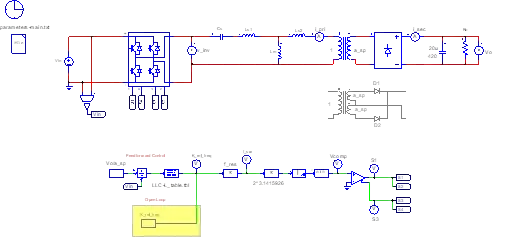
Fig 1. Example schematic in Altair PSIM.
Domain Conversion
PSIM has a tool built directly into its interface that allows users to convert freely from the s-domain to z-domain. Simply navigate to the utilities tab, choose s2z Converter, and enter the parameters for the s-domain transfer function. The dialog box, shown in Figure 2 below, displays the expected input parameters (based on the selected s-domain function type), sampling frequency, and conversion method selections. Users can enter all necessary values, using the block diagram representations as ‘blueprints’ for each function, and compute the outputs.
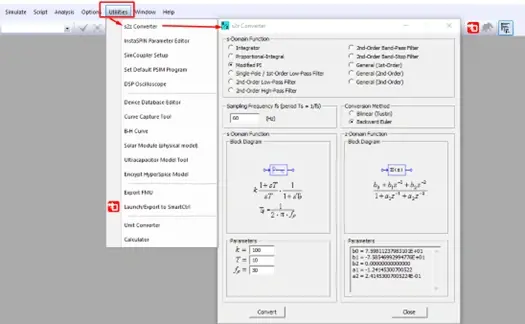
Fig 2. Domain Conversion tool in Altair PSIM.
Moving Connected Schematic Elements
Have you ever tried to move a resistor, capacitor, or some other component in your schematic after you have already connected to the rest of your circuit? It can often be quite frustrating, as it may lead to floating connections, unnecessary wires that need to be deleted, and the need for more connections to be manually drawn. This can become time consuming if moving a component with multiple connections or nodes. Luckily, Altair PSIM lets you choose whether to maintain those connections while moving a component: simply hold down the shift key when clicking on an element, and all wires will stay connected while that element is relocated. The animation in Figure 3 below shows a side-by-side comparison of using the shift key versus not using it.
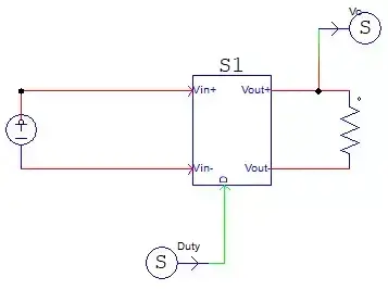
Fig 3. Comparison of moving components with connections not maintained (left) and connections maintained (right) in Altair PSIM.
Schematic Component Text Customization
Another feature of PSIM that makes it the elite schematic editor is its ability to customize and manipulate the text for every circuit element. Not only can users define unique names and values for every parameter, but there is also the option to display them alongside the corresponding component and customize how that information is displayed.
.gif)
Fig 4. Customizing component text elements in Altair PSIM.
The animation in Figure 4 above shows a demonstration of this process, which can be accomplished by selecting the desired circuit component and clicking the Tab key until the label or value of interest is reached. From there, users can relocate the displayed label or open its attributes and update the parameters.
Schematic Component Image Customization
Like the previous tip, users can also create a secondary image to represent components within circuit schematics. If users have a bitmap file of the desired image, they can upload that directly to PSIM, or generic shapes can be drawn with lines, arcs, and other 2D geometric tools. The access to this library is shown below in Figure 5.
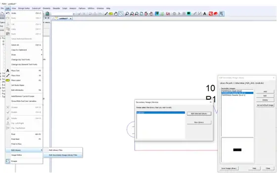
Fig 5. Accessing the secondary image library via the Edit menu in Altair PSIM.
Once users have navigated to the library, they can select a component that needs a new schematic image, upload or draw the new representation, and then update the ‘color’ of that component to implement the update throughout the schematic. The result of this is demonstrated below in Figure 6.
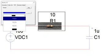
Fig 6. Using a custom image loaded into Altair PSIM’s secondary image library.
Exporting Schematic Images
Finally, once users have customized not only the electrical parameters of their schematic, but also its presentation, it’s important to be able to properly export and share your files with the entire team. However, if you are putting these results into a document or a presentation, most screenshot tools will result in a lower quality .jpg or .png. This may make the schematic challenging to read, but Altair PSIM has a solution, fortunately. Instead of some simple form of copy-and-paste, users should go to Edit > Copy to Clipboard > Metafile format, as seen in Figure 7.
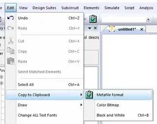
Fig 7. High-resolution export instructions for pasting into documents or presentations.
Once this is complete, users are ready to paste the high-resolution version of their schematic into a document or slide deck. In the following comparison, Figure 8, it can clearly be seen that this export tool results in a much clearer image, where the screenshot results in compression and loss of quality.
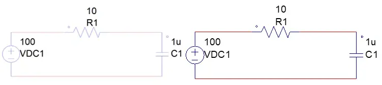
Fig 8. Comparison of screenshot (left) versus high-resolution export (right) in Altair PSIM.
That concludes this brief list of tips and tricks that make Altair PSIM even more user friendly than it already is. If you would like to learn more shortcuts like these, more about the overall capabilities of the software, or Altair’s portfolio of engineering simulation and solutions, please don’t hesitate to reach out to us here on our website. As always, check back often for more content like this and be sure to subscribe to our YouTube channel for even more video guides and walkthroughs.