TrueInsight
Siemens/Altair Channel Partner
Menu


Altair Feko and Formula 1 Communications Systems
Check out this post that shows how Formula 1 teams could use Altair Feko to help with the communication subsystems between the pit wall and the driver.
Formula One is exciting to take part in. Whether that means you are watching the race as a fan or actually taking part in the design and construction of these insanely powerful machines. Many spectators are aware of how much time and energy goes into the analysis of the aerodynamics of the body, the output of the engine, and the ability of the driver to effectively navigate one of these racecars, but there are other important systems that are not and cannot be neglected.
One such subsystem is the onboard communications, which is integral for the driver to communicate with the crew, and for the crew to receive live feedback regarding the state of other systems, such as various temperature or vibration data.

This kind of analysis is just one of many possible within the Altair suite of simulation tools, and this blog will cover one such example in the high-frequency three-dimensional electromagnetic analysis software Altair FEKO.
To demonstrate this tool’s functionality, we will walk through a simplified example of installing antennas on the body of an F1 car and viewing the performance of the devices. In reality, the number of antennas on a racecar like this can vary, but we will assume there are two antennas for this overview: one towards the front of the car for voice communications, and one towards the rear of the car for sensor data output.
Analysis Setup
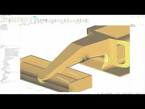
The first step in this process is to import the geometry of our vehicle into the CADFEKO workspace, which will allow us to view and edit the geometry, as well as add our electrical components and devices. Geometry can be created within the software, or imported from another tool, and multiple file types are supported, including Parasolid, STEP, IGES, CATIA, AutoCAD, and others. For this example, we are using an imported geometrical model as a Parasolid file.
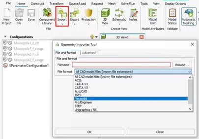 Fig 1. Importing Geometry into CADFEKO
Next, we will add our antennas to the vehicle. We will assume that both antennas are monopoles. There are a number of ways to go about this in the software, but we will use the most “out-of-the-box” method, which is to utilize the Monopole Antenna from the Component Library, which only requires the device’s operating frequency; after creating it, we can adjust the location of the antennas to the appropriate spots on the vehicle. The operating frequencies for these antennas were chosen to be within the allowable frequency range for communication devices at a racing event such as Formula One.
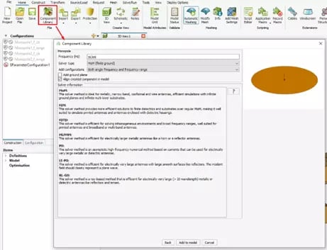 Fig 2. Using Component Library to add Monopole Antennas
Once we have imported our racecar and added our antennas, we can manipulate the locations of the devices and make any geometry changes that might be necessary. As I mentioned previously, we have two antennas on our simplified racecar: one on the nose and one towards the tail.
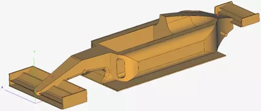
Fig 3. Racecar with Antennas added
One of the final steps before solving is to actually tell the software which results we are interested in. For this example, we want to see how the antennas behave, both operating at their intended frequency, and how they interact with each other over a range of frequencies. To complete this analysis, we will use the S-Parameter configuration, and we will sweep over a frequency range covering both of the devices’ operating points. This is fairly straightforward, as we can create an S-Parameter configuration in FEKO, which will allow us to define the antenna ports as the ports of our request.
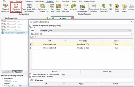 Fig 4. Defining S-Parameter simulation request
Solving
Finally, we can mesh and solve. FEKO has a built-in meshing tool that will automatically mesh your geometry for you. We will use the coarsest mesh option for this example, but there are many customization options, including general mesh sizes and finer localized meshing. From here, we can run the solver and launch POSTFEKO. Within this postprocessing tool, we have multiple ways to visualize the data we requested; depending on what we set up the simulation to do, we could display three-dimensional field data, surface currents, antenna patterns, and more. In this case, however, we will just use two cartesian graphs to examine the S-Parameters of the two antennas in our system.
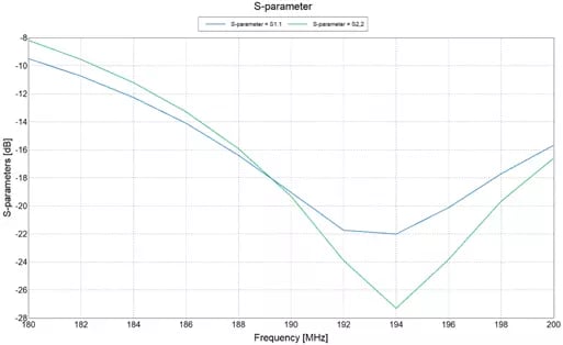 Fig 5. Reflection Coefficients of Antennas on racecar
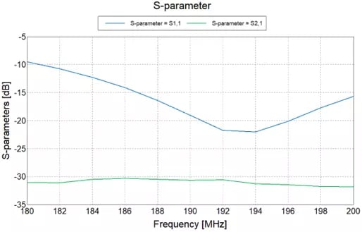 Fig 6. Coupling Coefficients of Antennas on racecar
From this point, the engineers on an F1 team could decide how to move forward with the project, whether that looks like changing the antennas, their locations, or something about the racecar itself. No matter what the next steps look like, simulation with the power of Altair FEKO and other tools in Altair portfolio expedites the process and gives engineers the information they need to deliver the best products possible. Remember to check back for more blogs like these here on our website and take a look at our YouTube page for videos showing overviews and tutorials for many of our tools. As always, if you have any questions or comments, please do not hesitate to reach out to us!