
TrueInsight
Siemens/Altair Channel Partner
Menu


Why Engineers in Aerospace Choose Solid Edge
In this post we look at the aerospace industry and how engineers have used Siemens Solid Edge to improve their workflows.
In the past we have talked about how the Altair solutions have been aiding aerospace design, more specifically from a simulation level. But whether you are building lightweight aerospace structures, high-speed robotic systems, or custom industrial equipment, your CAD platform plays a critical role in how efficiently your team operates. Many organizations still rely on legacy CAD systems that struggle with large assemblies, imported geometry, and rapid design changes. This can lead to longer development cycles, costly rework, and delayed product launches.
By combining synchronous and history-based modeling, strong performance, and deep integration with manufacturing and data management tools, Solid Edge has become a practical solution in this industry. In this article, we’ll look at how aerospace teams use Siemens Designcenter Solid Edge in real-world workflows, and why it continues to gain traction among modern engineering organizations.
Aerospace and Defense: Precision, Performance, and Compliance
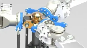
Fig 1: Rendering of helicopter propeller system in Solid Edge
The Challenges
Aerospace and Defense organizations operate in one of the most demanding engineering environments in that design teams must manage:
- Lightweight structures and material optimization
- Tight dimensional tolerances
- Large, highly detailed assemblies
- Strict documentation and certification requirements
- Complex supplier collaboration
Even small design changes can trigger major downstream impacts on manufacturing, testing, and compliance.
How Solid Edge Supports Aerospace Workflows
Solid Edge provides several capabilities that directly address these challenges:
Hybrid Modeling (Synchronous + Ordered)
Engineers can quickly create or modify imported supplier models and legacy parts without rebuilding feature histories. This is critical when working with multi-vendor data.
The Synchronous Technology built into Solid Edge is basically combining the speed and simplicity of direct modeling with the flexibility and control of parametric design.
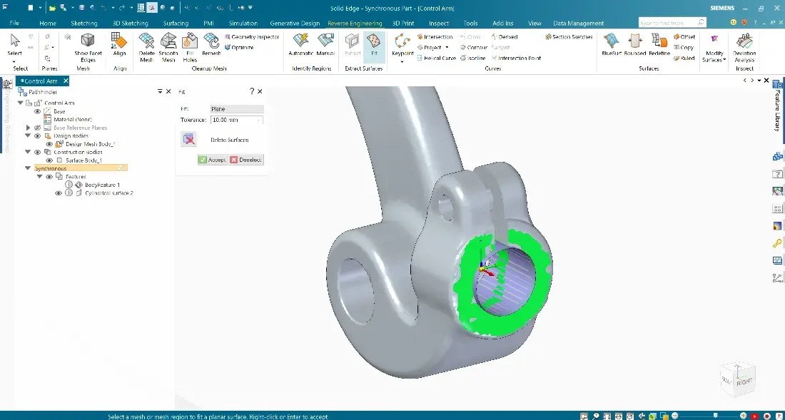
Fig 2: Import model preparation example in Solid Edge
Large Assembly Performance
Advanced memory management and lightweight representations allow engineers to work with full aircraft subsystems, such as fuselage sections, landing gear assemblies, or avionics racks, without sacrificing performance.
With assembly modeling, users can position complex subassemblies within master assemblies, and switch between simplified and detail views quickly to make day-to-day design operations much smoother.
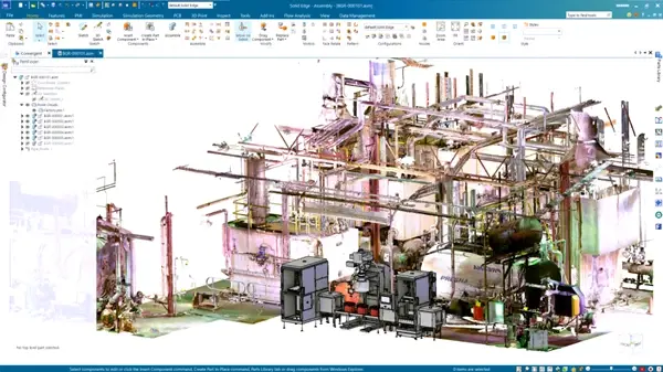
Fig 3: Large assembly example in Solid Edge
Model-Based Definition (MBD) and PMI
Solid Edge supports Product and Manufacturing Information (PMI), enabling teams to embed tolerances, notes, and inspection data directly in models. This supports digital thread initiatives and reduces drawing-related errors.
The Solid Edge Advanced PMI feature gives users the ability to automatically arrange and check dimensions on a 3D model quickly which results in higher quality PMI models.
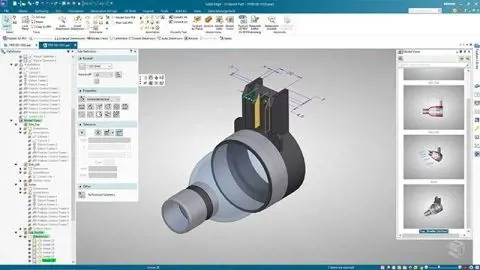
Fig 4: MBD example in Solid Edge
Integrated Simulation
Built-in structural analysis allows early validation of stiffness, vibration, and load response before physical prototypes are built. In addition, CFD solutions Simcenter FloEFD and Simcenter Flomaster work inside the Solid Edge interface for simple ease of use.
This means users have the ability to run simulations early in the design cycle to inform design changes whether it’s a structural or fluid-based simulation. This can greatly reduce the bottleneck when designs are sent for final analysis and ultimately out to manufacturing.
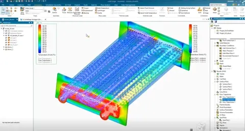
Fig 5: Simulation results in Solid Edge
Configuration Management
Engineers can manage multiple aircraft variants, payload configurations, or customer-specific options within a single design environment. Users can easily update relationships and constraints, whether you are modifying existing parts, or importing new assemblies.
Textual and symbolic representations of assembly components and their relationships, organized in an outline format, make it simple to find, activate, and control their display.
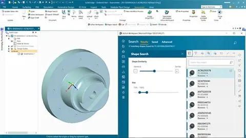
Fig 6: Integrated Teamcenter for Solid Edge
Other Solid Edge Aerospace Resources from Siemens
Siemens Case Study
Check out this real-world example from Werner Weitner, who use Solid Edge to develop special-purpose machines for aerospace applications: CAD with integrated FEA facilitates a fast track to validated designs.
“With built-in simulation, we are able to identify potential design problems earlier in the process and can react more quickly. As a result, we save a lot of time and money,” says Wolfgang Wiesent, Development Manager.
Talking Aerospace Today Podcast
You can also check out this great podcast from host Patty Husso, Global Marketing Manager from Siemens; Todd Tuthill, VP of Aerospace, Defense and Marine for SDIS and Dale Tutt VP of Industry Strategy for Siemens: The Rise of Software-Defined Aerospace. This episode covers shy systems engineering is becoming more business critical and other factors in the space sector that require software to be application specific.
On-Demand Webinar
This 50-minute webinar covers how companies are overcoming aerospace supply chain and product development challenges in the aerospace industry. Presenters are Chad Jackson, Chief Analyst & Content Director at Lifecycle Insights, and David Jackson, Business Development Manager for Solid Edge at Siemens.
As always, if you want to talk in more depth about Solid Edge or any Siemens/Altair solution, reach out to us and let us know.